317
Present Position Preset
Section 8-3
8-3
Present Position Preset
PRESENT POSITION PRESET changes the present position to any position
and then establishes the origin.
8-3-1
Outline of Operation
When the PRESENT POSITION PRESET Bit is turned ON, the present posi-
tion is changed to the value set as the position command value in the Axis
Operating Output Memory Areas. during present position preset, the Busy
Flag is ON (1 cycle time min.). The Busy Flag turns OFF to indicate that pre-
set operation has been completed. After this, the origin is established. If the
present position is changed to “0,” then that position will become the origin.
8-3-2
Data Settings for Present Position Preset
A simple explanation of the main parameters and data used to execute
PRESENT POSITION PRESET is provided here. For details on command
units, refer to
7-2 Control Units
.
The setting units for parameters and data depend on the specified command
unit.
Servo Parameter Area
Command Unit Parameters
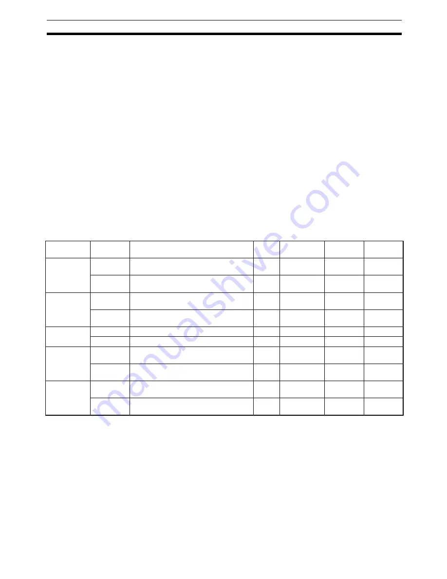
The command unit default setting is pulses.
Model
Parameter
No.
Parameter name
Unit
Setting
range
Parameter
size
Default
setting
R88D-KN
@
-
ML2
Pn009
Electronic gear ratio numerator
---
1 to
1073741824
4
1
Pn010
Electronic gear ratio denominator
---
1 to
1073741824
4
1
R88D-GN
@
-
ML2
Pn205
Electronic gear ratio G1 (numerator)
---
1 to
1073741824
4
1
Pn206
Electronic gear ratio G2 (denominator)
---
1 to
1073741824
4
1
R88D-WT
@
Pn202
Electronic gear ratio G1 (numerator)
---
1 to 65535
2
4
Pn203
Electronic gear ratio G2 (denominator)
---
1 to 65535
2
1
R88D-WN
@
-
ML2
Pn20E
Electronic gear ratio G1 (numerator)
---
1 to
1073741824
4
4
Pn210
Electronic gear ratio G2 (denominator)
---
1 to
1073741824
4
1
SMART-
STEP Junior
Pn20E
Electronic gear ratio G1 (numerator)
---
1 to
1073741824
4
1
Pn210
Electronic gear ratio G2 (denominator)
---
1 to
1073741824
4
1
Содержание CJ1W-NC271 - 12-2009
Страница 2: ......
Страница 4: ...iv ...
Страница 6: ...vi ...
Страница 22: ...xxii ...
Страница 58: ...30 Starting Operation Section 2 2 ...
Страница 244: ...216 Axis Operating Input Memory Areas Section 4 8 ...
Страница 264: ...236 Transferring Servo Parameters Section 5 3 ...
Страница 396: ...368 Linear Interpolation Section 9 7 ...
Страница 648: ...620 List of Error Codes Appendix D ...
Страница 674: ...646 Additional Functions for the CJ1W NCF71 MA Appendix F ...
Страница 684: ...656 Index ...
Страница 686: ...658 Revision History ...


