3 Installation and Commissioning
368
7UM62 Manual
C53000-G1176-C149-3
The polarity of the current connections and the parameterized polarity are taken into
consideration when the angles are displayed. Thus, if all three angles differ by 180°
from the theoretical value, the polarity of one complete transformer set is wrong. This
can be corrected by checking and changing the corresponding plant parameters:
Address
for the primary winding,
Address
for the secondary winding,
Differential and
Restraint Currents
Before the tests with symmetrical currents are terminated, the differential and restraint
currents are checked. Even though the tests which have been carried out so far should
have revealed most of the possible connection errors, matching errors or wrong vector
group allocations cannot be ruled out.
Switch to the operational measured values to read out the calculated values. When
assessing the currents, note that the differential and restraint values are referred to
the rated current of the protected object. This fact should be kept in mind when
comparing them to the test currents.
If considerable differential currents occur, recheck the following parameters:
For transformer protection (as per Section 2.12.2.2): addresses
(matching of winding 1),
(matching and vector group
of winding 2);
For generator or motor protection (as per Section 2.12.2.2): addresses
(matching of machine ratings);
The symmetrical current tests are now completed. Disconnect the protected object
(shut down generator) and earth it, remove the test equipment.
Switch the differential protection to being operative (address
=
ON
); it works now as a short-circuit protection for all subsequent tests.
3.4.4
Checking the Earth Current Differential Protection
Preparation
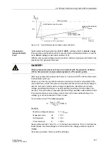
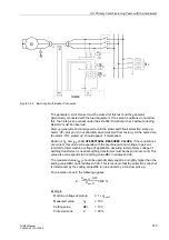
The primary test checks the correct integration of the 7UM62 into the system, espe-
cially the CT connection. Before commencing any primary tests, make sure that the
configured object is actually the one you want to protect. To do so, verify the settings
used in the configuration of the protection function, in Power System Data 1 and in the
protection function itself.
Set the earth current differential protection (address
) to
, or interrupt the trip command lines.
Table 3-25
Displayed Phase Angle Dependent on the Protected Object (Three-Phase)
Protect. Object
→
Generator/Motor
Transformer with Vector Group Numeral
1
)
↓
Phase Angle
0
1
2
3
4
5
6
7
8
9
10
11
ϕ
L1S2
180°
180°
150° 120°
90°
60°
30°
0°
330° 300°
270° 240°
210°
ϕ
L2S2
60°
60°
30°
0°
330°
300° 270°
240° 210° 180°
150° 120°
90°
ϕ
L3S2
300°
300°
270° 240° 210°
180° 150°
120°
90°
60°
30°
0°
330°
1
) Values are valid for measurement if the higher voltage side is defined as side 1; when measuring from the lower voltage side, 360°
minus the stated angle is valid

