A.2 General Diagrams (IEC)
483
7UM62 Manual
C53000-G1176-C149-3
7UM622
∗
–
∗
D/E
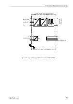
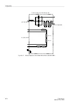
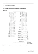
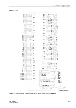
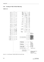
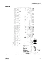
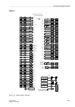
Figure A-21 General Diagram 7UM622
∗
−
∗
D/E (Panel Flush Mounting or Cubicle Installation)
Power
Earthing at rear
supply
wall of housing
F1
F2
( )
~
+
-
Life status
F4
F3
1 2
3 2
Interference suppression
capacitors at the
relay contacts
Q1
Q2
I
L1S2
Q3
Q4
I
L2S2
Q5
Q6
I
L3S2
R13
R14
U
E
R15
R17
U
L1
R18
U
L2
R16
U
L3
F5
F6
BI1
F8
F9
F10
F7
BI2
BI4
BI5
BI3
K9
K10
BI6
K11
K12
BI7
N4
N6
N5
N3
BI11
BI12
BI10
N7
N8
BI13
N9
N10
BI14
N11
N12
BI15
R3
R4
BO3
R6
BO4
R5
BO5
R2
BO2
R1
BO1
R8
R7
1 2
3 2
BO6
R9
R10
BO7
R11
R12
BO8
K6
K5
1 2
3 2
BO11
P17
P18
BI8
N1
N2
BI9
P6
P7
BO14
P8
BO15
P5
BO16
P9
P10
BO17
P11
P12
BO18
P13
P14
BO19
P15
P16
BO20
Q7
Q8
I
EE2
P4
P3
1 2
3 2
BO13
System interface
or analog output
B
A
Front oper. interface
Time synchronization
Service port
C
Analog output
D
F
o
r
the
pi
n
a
ss
ig
n
m
ent
of
th
e
int
er
fa
c
e
s
s
ee
tables
to
in
sub
s
ect
ion
K13
K14
TD1
K15
K16
TD2
(+)
(–)
(+)
(–)
K17
K18
TD3
(+)
(–)
J1
J2
I
L1S1
J3
J4
I
L2S1
J5
J6
I
L3S1
J7
J8
I
EE1
K1
K2
BO9
K3
K4
BO10
K8
K7
1 2
3 2
BO12
contact
Ceramic, 4.7 nF250 V
or Thermobox
or Thermobox

