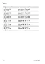
Functions
292
7UM62 Manual
C53000-G1176-C149-3
−
U/f th.
Overtemperature caused by an overexcitation, in % of the tripping
overtemperature,
−
Coolant temperature (or ambient temperature)
In addition, the following may be available:
Min/Max Values
1
)
−
Minimum and maximum values for the positive-sequence components I
1
and U
1
,
the active power P, reactive power Q, in primary values, of the frequency and of the
3rd harmonic content in the displacement voltage, in secondary values U
3.H
.
Included are the date and time they were last updated. The minimum/maximum
values can be reset via binary inputs or, in the delivery status of the device, also via
the F4 function key.
Energy, Metered
Values
1
)
−
W
p
, W
q
, metered values of the active and reactive energy in kilowatt, megawatt or
gigawatt hours primary or in kVARh, MVARh or GVARh primary, separately
according to the input (+) and output (–), or capacitive and inductive.
The calculation of the operational measured values is also executed in case of an
existing fault. The values are updated in intervals of
≥
0.3 s and
≤
1 s.
Transfer of
Measured Values
Measured values can be transferred via the interfaces to a central control and storage
unit.
Setpoint
Monitoring
SIPROTEC
®
7UM62 allows to set warning levels for important measured and counter
values. When a programmed limit value is exceeded (or fallen below), a message is
generated that is output as an operational annunciation and can — like all operational
annunciations — be masked to both output relays and LEDs and transmitted through
the interfaces. In contrast to the actual protective functions, such as time-overcurrent
protection or overload protection, this monitoring program executes in the background
and may not respond promptly in case of a fault if the measured values change rapidly
and protective functions pick up. Moreover, since a message is not generated until the
set limit value has been exceeded several times, these monitoring functions cannot
respond immediately before a device trip.
In the7UM62, only the limit value of the undercurrent protection
IL<
is configured
when the device is delivered from the factory. More limit values can be configured if
their measured and metered values have been set accordingly in CFC) see
SIPROTEC
®
4 System Manual).
2.45.3 Oscillographic Fault Recording (Waveform Capture)
Terminology
Please be aware of the fact that we use different terms for the above-mentioned
function: (Oscillographic) Fault Recording, Oscillographic Recording, Wave Form
Capture. However, all terms have the same meaning. The corresponding fault buffer
in DIGSI® 4 is called Trip Log.
General
The Multifunctional Protection 7UM62 is equipped with a fault memory sampling either
the instantaneous values or the r.m.s. values of various measured quantities to store
them in a circulating buffer. The instantaneous values of measured values
1.) only in the 7UM62**–*****–3***

