Functions
56
7UM62 Manual
C53000-G1176-C149-3
Coolant
Temperature/
Ambient
Temperature
The thermal model of the 7UM62 considers an external temperature value. Depending
on the application, this temperature can be the coolant or ambient temperature or, in
the case of gas turbines, the entry temperature of the cold gas. The temperature to be
considered can be fed in by one of the following:
−
Measuring transducer (TD 2)
−
Profibus DP interface/Modbus
−
Temperature detection unit (Thermobox, RTD 1)
An external temperature sensor measures e.g. the coolant temperature and converts
it into a current or voltage that is proportional to the temperature. This output quantity
can be fed into the 7UM62 via the integrated measuring transducer TD 2. If a signal
level between 4 mA and 20 mA is used, the measuring circuit for temperature input
can additionally be monitored for interruptions. If the measured currents of the external
amplifier drops to less than 2 mA, the relay outputs an alarm, and switches at the same
time to the internal coolant temperature of 40 °C (which is the temperature assumed
if there is no coolant temperature detection).
The ambient or coolant temperature can also be detected by an external temperature
sensor, digitized and fed to the 7UM62 via the Profibus DP interface/ Modbus.
If a temperature supervision feature is implemented by means of the thermobox (see
section 2.42) the RTD1 input can be used for temperature inclusion considered by the
thermal replica.
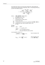
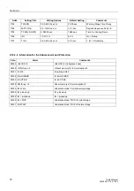
Where the coolant temperature detection exists, the maximum permissible current
I
max
is influenced by the temperature difference of the coolant. If the ambient or
coolant temperature is low, the machine can support a higher current than it does
when the temperature is high.
Current Limiting
In order to avoid that the thermal overload protection reaches extremely short trip
times on occurrence of high short-circuit currents (and on selection of a small time
constant) and thus perhaps affects the time grading of the short-circuit protection, it is
possible to determine a current limiting of the overload protection. Currents exceeding
the value specified at parameter
are limited to this value. For
this reason, they do not further reduce trip time in the thermal image.
Standstill Time
Constant
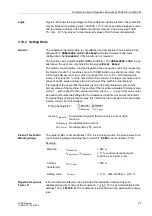
The above differential equation assumes a constant cooling that is expressed by the
time constant
τ
= R
th
· C
th
(thermal resistance and thermal capacitance). In a self-
ventilated machine, however, the thermal time constant at standstill can differ
considerably from the constant of a steadily running machine, since with the machine
running the ventilation provides for cooling whereas at standstill only the natural
convection occurs.
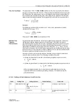
Therefore, two time constants must be considered in such cases for setting.
In this context, a machine standstill represents the moment when the current falls
below the threshold value
(see side title”Current Flow Monitoring”
in Section 2.3).
Blocking
The thermal overload protection feature may be reset via a binary input (”
”). The current-induced overtemperature value is reset to zero. The
same is achieved by entering a blocking (”
”); in that case the
overload protection is blocked completely, including the current warning stage.
When machines must be started for emergency reasons, operating temperatures
above the maximum permissible operating temperatures can be allowed by blocking

