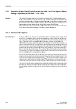
Sensitive Rotor Earth Fault Protection with 1 to 3 Hz Square Wave Voltage Injection (ANSI 64R - 1 to 3 Hz)
209
7UM62 Manual
C53000-G1176-C149-3
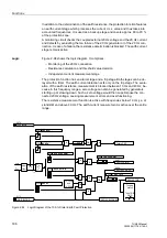
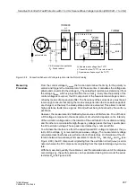
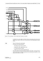
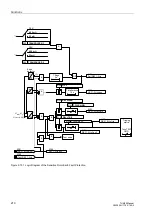
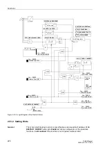
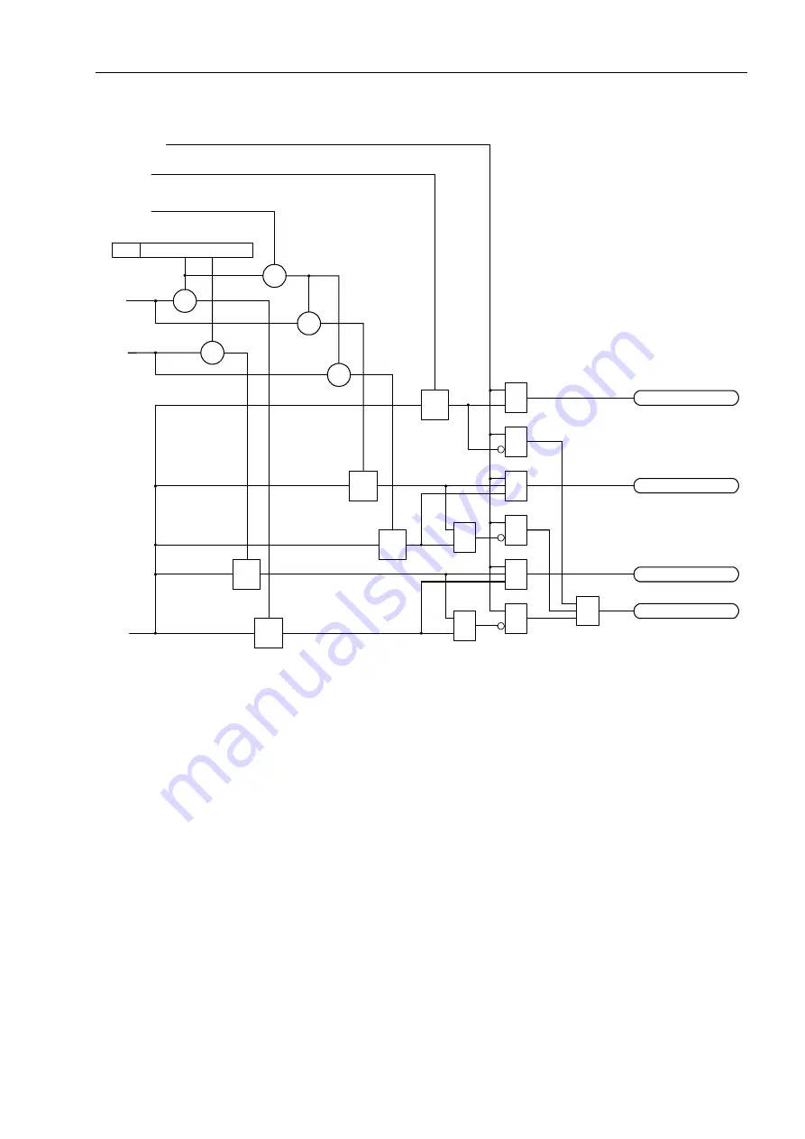
Figure 2-100 Logic Diagram of the Rotor Earth Fault Protection in Test Mode
In addition, the control voltage is monitored. If the control voltage is found to be miss-
ing or too low, a failure of the control unit is assumed (see also logic diagram in Figure
2-100).
Logic
Figure 2-100 shows the logic diagram.
It comprises the following elements:
−
Monitoring of the control unit 7XT71
−
Supervision of the measurement circuit
−
Two-stage protection function
−
Effects of the rotor earth fault protection test
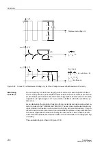
If the earth resistance drops below the high-resistance stage RE<, a warning message
will normally be issued. If it drops below the second, low-resistance stage RE<<, a trip
signal is issued after a short time.
6107 TEST RESISTOR
+
X
X
X
X
&
&
&
&
&
&
&
RE<
&
RE<
RE>
RE>
RE>
OR
Test mode
100 k
Ω
0.7
1.3
RE
20 k
Ω
(Series resistor = R
S
/2)
5411
2 Cir. open
5410
1 Cir. open
5408
Test REF PASSED
5409
Test REF Fail.

