


A Appendix
484
7UM62 Manual
C53000-G1176-C149-3
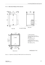
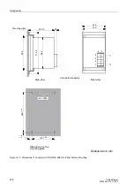
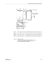
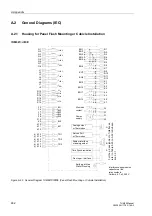
A.2.2
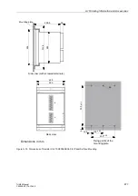
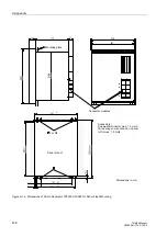
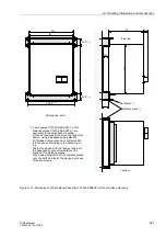
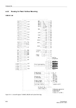
Housing for Panel Surface Mounting
7UM621
∗
–
∗
B
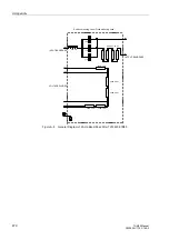
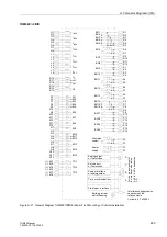
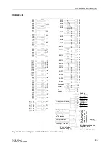
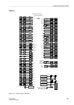
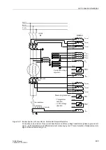
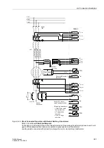
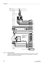
Figure A-22 General Diagram 7UM621
∗
–
∗
B (Panel Surface Mounting)
Power
Earthing at side
supply
wall of housing
15
16
( )
~
+
-
Life status
52
51
contact
1 2
3 2
Interference suppression
capacitors at the
relay contacts,
25
50
I
L1S2
24
49
I
L2S2
23
48
I
L3S2
21
46
U
E
20
19
U
L1
44
U
L2
45
U
L3
58
57
BI1
55
54
83
56
BI2
BI4
BI5
BI3
88
63
BI6
87
62
BI7
73
98
BO3
72
BO4
97
BO5
99
BO2
74
BO1
71
96
1 2
3 2
BO6
95
70
BO7
94
69
BO8
65
90
1 2
3 2
BO11
22
47
I
EE2
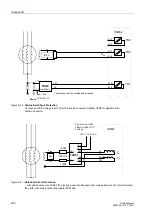
System interface
or analog output
B
Front oper. interface
Service port
C
Analog output
D
F
o
r
the
pin
a
ssignm
ent
of
th
e
int
er
fa
c
e
s
s
ee
tables
and
in
subs
ect
ion
14
39
I
L1S1
13
38
I
L2S1
12
37
I
L3S1
11
36
I
EE1
92
67
BO9
91
66
BO10
64
89
1 2
3 2
BO12
86
61
TD1
85
60
TD2
(+)
(–)
(+)
(–)
84
59
TD3
(+)
(–)
2
27
3
29
28
4
1
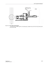
Time synchronization
IN 12 V
IN SYNC
COM SYNC
COMMON
IN 24 V
Screen
IN 5 V
terminal (26)
Ceramic, 4.7 nF, 250 V
Earthing
or Thermobox
or Thermobox
*)
*) optical only IEC


