Functions
218
7UM62 Manual
C53000-G1176-C149-3
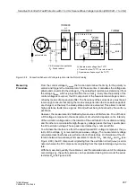
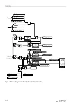
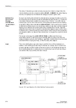
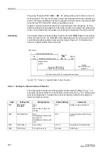
Although the heat distribution at the rotor cage bars can range widely during motor
starting, the different maximum temperatures in the rotor do not necessarily affect the
motor restart inhibit (see Figure 2-104). It is much more important to establish a
thermal profile, after a complete motor start, that is appropriate for the protection of the
motor’s thermal condition. Figure 2-104 shows, as an example, the heating processes
during repeated motor starts (three starts from cold operating condition), as well as the
thermal reproduction by the protective relay.
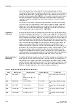
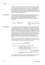
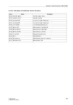
Restarting Limit
If the rotor temperature has exceeded the restarting limit, the motor cannot be
restarted. When the rotor temperature goes below the restarting limit, that is, when
exactly one start becomes possible without exceeding the excessive rotor
temperature limit, the blocking signal is terminated. Therefore the restarting
temperature
Θ
Re.Inhib
, related to the maximum permissible rotor overtemperature is
expressed as:
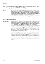
Restarting Times
The motor manufacturer allows a maximum number of starting attempts under cold
(n
cold
) and warm (n
warm
) conditions. Afterwards the motor cannot be restarted but
must be allowed some time — the restarting time — for the rotor to cool down. This
temperature behaviour is provided for in the protection as follows: After each motor
shutdown, a temperature equilibrium time (address
) is started which
takes into account the different temperatures of different motor parts at the moment of
shutdown. During the rotor temperature equilibrium time, the thermal profile is not
updated but kept constant to model the equilibrium taking place in the rotor. After that,
the thermal profile cools down with a rotor time constant multiplied by
extension
factor). During the equilibrium time the motor cannot be restarted. As soon as
temperature sinks below the restarting threshold, the next restart attempt can be
made.
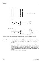
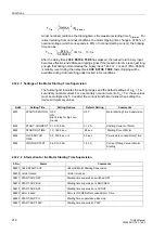
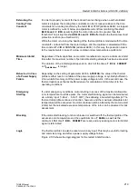
The entire time that must elapse before motor starting can resume is equal to the
equilibrium time and the amount of time, calculated via the thermal model, that it takes
for the rotor temperature to decrease to the reset temperature level:
The operational measured value T
ReInhib time
(to be found in the overload measured
values) shows the time remaining until the next restart is permissible.
n
cold
2
3
4
Θ
Re.Inhib
[%]
50 %
66.7 %
75 %
Θ
ReInhib
%
[ ]
n
cold
1
–
n
cold
--------------------- 100 %
⋅
=
T
ReInhib time
T
Equilibrium
k
τ
τ
LR
ln
Θ
pre
n
cold
⋅
n
cold
1
–
-----------------------------
⋅
⋅
+
=
where T
Equilibrium
– Rotor temperature equilibrium time address
k
τ
– Extension factor for the time constant =
address
or
address
τ
R
– Rotor time constant, internally calculated:
τ
R
= t
Start
⋅
(n
cold
– n
warm
)
⋅ Ι
start
2
where
t
Start
= Starting time in s
Ι
Start
= Starting current in pu
Θ
pre
– Thermal profile at the moment of motor shutdown (depends on the
operating state)

