4 Technical Data
400
7UM62 Manual
C53000-G1176-C149-3
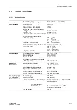
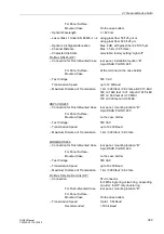
– Optical Wavelength
λ =
820 nm
– Laser Class 1 Under EN 60825–1/ –2 Using glass fiber 50/125 µm or
Using glass fiber 62.5/125 µm
– Optical Link Signal Attenuation
Max. 8 dB, with glass fiber 62.5/125 µm
– Channel Distance
Max. 1.5 km (0.95 miles)
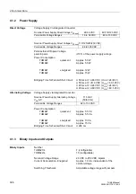
DNP3.0 Fibre Optical Link
– Connection
ST–Connector,
For Flush-Mounted Case
rear panel, mounting location “B“
For Panel Surface-
Mounted Case
On the case bottom
– Transmission Speed
Up to 19200 Baud
– Optical Wavelength
λ =
820 nm
– Laser Class 1 Under EN 60825–1/ –2 Using glass fiber 50/125 µm or
Using glass fiber 62.5/125 µm
– Optical Link Signal Attenuation
Max. 8 dB, with glass fiber 62.5/125 µm
– Channel Distance
Max. 1.5 km (0.95 miles)
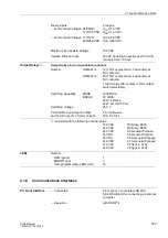
MODBUS Fibre Optical Link
– Connection
ST–Connector,
For Flush-Mounted Case
Rear panel, mounting location “B“
For Panel Surface-
Mounted Case
On the case bottom
– Transmission Speed
Up to 19200 Baud
– Optical Wavelength
λ =
820 nm
– Laser Class 1 Under EN 60825–1/ –2 Using glass fiber 50/125 µm or
Using glass fiber 62.5/125 µm
– Optical Link Signal Attenuation
Max. 8 dB, with glass fiber 62.5/125 µm
– Channel Distance
Max. 1.5 km (0.95 miles)
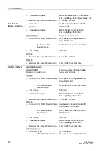
Analog Output Module (Electrical)
2 ports with 0 mA to 20 mA
– Connection for Flush Mounted Case
Rear panel, mounting location “B“ and “D”
9-pin DSUB Port RS 485
For Panel Surface-
Mounted Case
On the case bottom
– Test Voltage
500 VAC
Clock
– Time Synchronization
DCF77/IRIG B–Signal
– Connection For Flush-mounted Case Rear panel, mounting location “A“
9-pin DSUB port
For Panel Surface-
At the terminal on the case bottom
Mounted Case
– Signal Rated Voltage
Selectable 5 V, 12 V or 24 V

