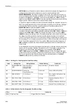
Functions
304
7UM62 Manual
C53000-G1176-C149-3
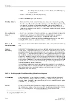
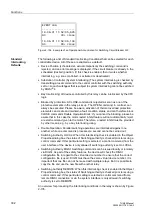
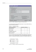
Figure 2-136 DIGSI
®
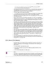
4 Dialog Box for Setting the Interlocking Conditions
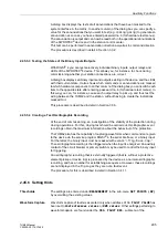
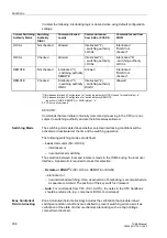
The display shows the configured interlocking reasons. The are marked by letters ex-
plained in the following Table 2-21:
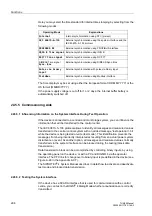
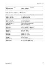
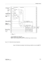
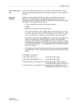
Figure 2-137 shows all interlocking conditions (which usually appear in the display of
the device) for three switchgear items with the relevant abbreviations explained in
Table 2-21. All parametrized interlocking conditions are indicated (see Figure 2-137).
.
Figure 2-137 Example of Configured Interlocking Conditions
Table 2-21
Interlocking Commands
Interlocking Commands
Abbreviation
Message
Switching Authority
L
L
System Interlock
S
S
Zone Controlled
Z
Z
Target State = Present State
(check switch position)
P
P
Block by Protection
B
B
Q8 Close/Open S – Z P B
Interlocking 01/03
--------------------
Q
0 Close/Open S – Z P B
Q1 Close/Open S – Z P B


