A Appendix
498
7UM62 Manual
C53000-G1176-C149-3
A.4.1
Connection Examples for RTD-Box
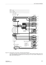
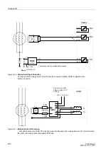
Figure A-40 Simplex operation with one RTD-Box
above: optical design (1 FO); below: design with RS485
Figure A-41 Half-duplex operation with one RTD-Box
above: optical design (2 FOs); below: design with RS485
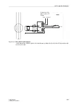
Figure A-42 Half-duplex operation with two RTD-Boxes
above: optical design (2 FOs); below: design with RS485
7UM62
A’
A
B
B’
7XV566
RTD-Box
7XV5650
FO/RS485
Converter
A
B
T1
Port D
A’
A
B
B’
7XV566
RTD-Box
7UM62
Port C or D
A
B
Bus number: 00
A’ and B’ jumpers for
the terminating resis-
tors
Bus number: 00
A’ and B’ jumpers for
the terminating resis-
tors
7UM62
7XV5650
FO/RS485
Converter
A
B
T1
Port D
A’
A
B
B’
7XV566
RTD-Box
7UM62
Port C or D
A
B
R1
A’
A
B
B’
7XV566
RTD-Box
Bus number: 01
A’ and B’ jumpers for
the terminating resis-
tors
Bus number: 01
A’ and B’ jumpers for
the terminating resis-
tors
7UM62
A
B
7XV566
RTD-Box
Bus number: 01
A
B
T1
Port C
1
)
2
)
for 7SJ64 optionally port C or D
A
B
7XV566
RTD-Box
Bus number: 01
7UM62
Port C
2
)
A
B
R1
A’
A
B
B’
7XV566
RTD-Box
A’
A
B
B’
7XV566
RTD-Box
Bus number: 02
A’ and B’ jumpers for
the terminating resis-
tors
Bus number: 02
A’ and B’ jumpers for
the terminating resis-
tors
7XV5650
FO/RS485
Converter
1
)
for 7SJ64 port D

