3.1 Installation and Connections
317
7UM62 Manual
C53000-G1176-C149-3
Nominal Currents
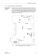
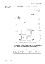
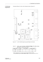
The rating of the current input transformers of the device can be changed to 1 A or 5 A
with jumper settings that determine the secondary loading of the transformers. When
the device is delivered, these jumpers are set according to the name-plate sticker. The
physical arrangements of these jumpers that correspond to the different current
ratings are described below, Subsection 3.1.3.3 “C-I/O–2 Input/Output Board” for side
1 and „C-I/O–6 Input/Output Board“ for side 2.
All the relevant jumpers of one side must be in the same position, i.e. there must be
one of the jumpers X61 through X64 for each of the input transformers and additionally
the common jumper X60.
If nominal current ratings are changed, then the new ratings must be altered under
Addresses
or 0212
in the
Power
System Data1
(see Sub-section 2.3).
Control Voltages
for Binary Inputs
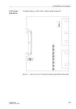
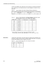
When the device is delivered from the factory, the binary inputs are set to operate with
a DC control voltage that corresponds to the rated DC voltage of the power supply. In
general, to optimize the operation of the inputs, the pickup voltage of the inputs should
be set to most closely match the actual control voltage being used. In some cases
such as the one described in the note below, lowering the pickup voltage might be
necessary. Each binary input has a pickup voltage that can be independently
adjusted; therefore, each input can be set according to the function performed.
A jumper position is changed to adjust the pickup voltage of a binary input. The
physical arrangement of the binary input jumpers in relation to the pickup voltages is
explained below, Sub-section 3.1.3.3.
Changeover
Contacts
Input/output modules can have relays that are equipped with changeover contacts.
The device terminals can be connected to either the NC or the NO contact; the choice
is made by jumpers. The relays and cards for which this applies are stated in Section
3.1.3.3 under the side titles "C–I/O–2 Input/Output Board" and "C–I/O–6 Input/Output
Board".
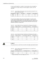
Measuring
Transducers
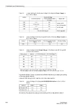
The measuring transducers TD 1 (e.g. for DC voltage/DC current protection) and TD
2 (e.g. for input of the temperature for the overload protection) allow to select whether
voltages or currents will be processed as input quantities. To change the default
setting (measured quantities will be voltages), a few jumpers must be moved. An
overview of the jumper settings is given in the Tables 3-14 and 3-15 in Section 3.1.3.3
under the side title “C–I/O–6 Input/Output Board“.
Note:
The jumper settings must correspond to the secondary device currents configured at
addresses
and
. If they do not, the device is blocked and outputs an alarm.
Note:
If the 7UM62 performs trip circuit monitoring, two binary inputs, or one binary input and
a resistor, are connected in series. The pickup voltage of these inputs must be less
than half of the nominal DC voltage of the trip circuit.

