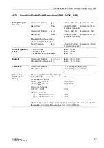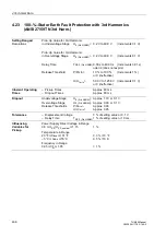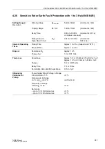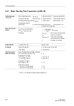
4.33 Additional Functions
449
7UM62 Manual
C53000-G1176-C149-3
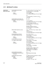
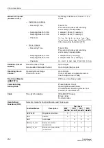
P, Real power (with sign) in kW (MW or
GW) primary, and in % S
Nom
- Range
0 % to 120 % S
Nom
- Tolerance
1 %
±
0.25 % S
N
with S
Nom
=
√
3 · U
Nom
· I
Nom
Q, Reactive power (with sign) in kVAr
(MVAr or GVAr) primary and in % S
Nom
- Range
0 % to 120 % S
Nom
- Tolerance
1 %
±
0.25 % S
N
with S
Nom
=
√
3 · U
Nom
· I
Nom
Operating Measured Values
cos
ϕ
(p.f.)
for Power Factor
- Range
–1 to +1
- Tolerance
1 %
±
1 Digit
Operating Measured Values
ϕ
for Power Angle
- Range
–90° to +90°
- Tolerance
0.1°
Counter Values for Energy
Wp, Wq (real and reactive energy)
in kWh (MWh or GWh) and in kVARh
(MVARh or GVARh)
- Range
8
1
/
2
digits (28 bit) for VDEW protocol
9
1
/
2
digits (31 bit) in the unit 7UM62
- Tolerance
1 %
±
1 Digit
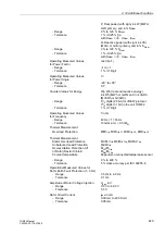
Operating Measured Values
f in Hz
for Frequency
- Range
40 Hz < f < 65 Hz
- Tolerance
10 mHz at U > 0.5
⋅
U
N
Thermal Measurement
Overload Protection
Θ
/
Θ
Trip
,
Θ
/
Θ
Trip L1
,
Θ
/
Θ
Trip L2
,
Θ
/
Θ
Trip L3
Thermal Measurement
Stator Overload Protection
Θ
S
/
Θ
L1Trip,
Θ
S
/
Θ
L2Trip,
Θ
S
/
Θ
L3Trip
Unbalanced Load Protection
Θ
i2
/
Θ
Trip
Overexcitation Protection U/f
Θ
U/f
/
Θ
Trip
of Rotor (Restart Inhibit)
Θ
Rot
/
Θ
Trip
Coolant temperature
Depends on connected temperature sensor
- Range
0 % to 400 %
- Tolerance
5 % class accuracy per IEC 60255-8
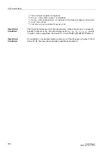
Operational Measured Values for
Rotor Earth Fault Protection (1–3 Hz)
- Range
0.5 Hz to 4.0 Hz
- Tolerance
0.1 Hz
Amplitude of Rotor Voltage Injection
U
gen
in V
- Range
0.0 V to 60.0 V
- Tolerance
0.5 V
Rotor Circuit Current
I
gen
in mA
- Range
0.00 mA to 20.00 mA
- Tolerance
0.05 mA


