3 Installation and Commissioning
330
7UM62 Manual
C53000-G1176-C149-3
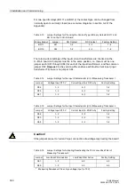
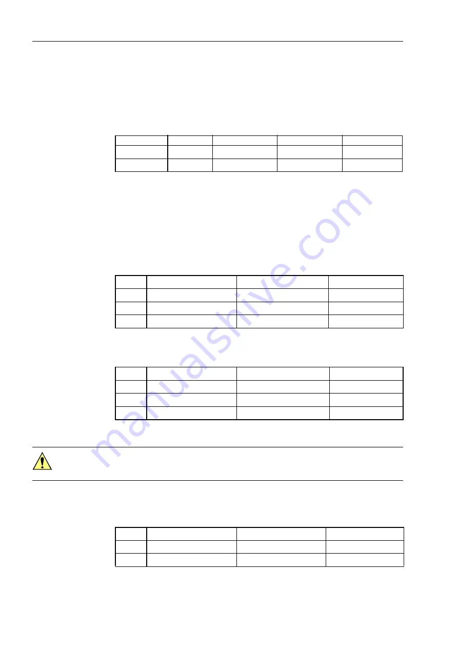
For two specific relays (BO 11 and BO 12) the contact type can be changed from
normally open to normally closed (see overview diagrams in section A.2 of the
Appendix):
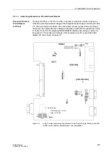
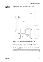
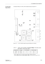
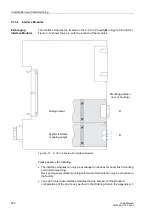
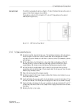
The rated current settings of the input current transformers are checked on the
C–I/O–6 board. All jumpers must be in the same position, i.e. there must be one
jumper each (X61 through X64) for each of the input transformers, and the common
jumper X60. However: In the version with sensitive earth fault current input (input
transformer T8) there is no jumper X64.
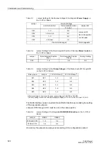
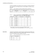
Table 3-13
Jumper Settings for Choosing the Contact Type of Binary Outputs BO 11 and
BO 12 on the C–I/O–6 Board
Binary Output
Jumper
NO Contact
NC Contact
Factory Setting
BO 11
X41
1–2
2–3
1–2
BO 12
X42
1–2
2–3
1–2
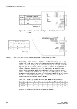
Table 3-14
Jumper Settings for the Input Characteristic (U/I) of Measuring Transducer 1
Jumper
Voltage Input
±
10 V
Current Input (4–20/20 mA)
Factory Setting
X94
1–2
2–3
1–2
X95
1–2
2–3
1–2
X67
1–2
2–3
1–2
Table 3-15
Jumper Settings for the Input Characteristic (U/I) of Measuring Transducer 2
Jumper
Voltage Input
±
10 V
Current Input (4–20/20 mA)
Factory Setting
X92
1–2
2–3
1–2
X93
1–2
2–3
1–2
X68
1–2
2–3
1–2
Caution!
If the jumpers are set to “current” input, connection of a voltage may destroy the board!
Table 3-16
Jumper Settings for Activating/Deactivating the 10 Hz Low-Pass Filter of
Measuring Transducer 3
*
*
Measuring transducer 3 has only a voltage input (± 10 V)
Jumper
Low-Pass Filter Inactive
Low-Pass Filter Active
Factory Setting
X91
1–2
2–3
2–3
X69
1–2
2–3
2–3


