3 Installation and Commissioning
370
7UM62 Manual
C53000-G1176-C149-3
If there are deviations, a connection error can be normally assumed. If necessary,
modify the wiring, or, in Power System Data 1, the allocation of the CT starpoint for
the phase CTs or the earth CT I
EE2
. For the phase CTs, keep in mind that they are
also used by other protection functions, such as the differential current protection, and
check for possible interaction. If the differential current protection has already been
checked, and the CTs of side 1 and 2 are used for the earth current differential protec-
tion as well, the above errors can be excluded. If the I
EE2
input is used, a wrong po-
larity of the connections is not uncommon. Check the connection and/or the starpoint
allocation in Power System Data 1 (address
). The default set-
ting assumes that terminal Q7 is looking towards the protected object.
If there are deviations in the measured values, the measured quantities are probably
not properly matched. Check the parameter settings of the protected object and of the
CTs in Power System Data 1. To do so, proceed as follows:
−
Shut down and earth generator
−
Check and correct connections, if necessary, or modify settings in Power System
Data 1
−
Repeat measurement
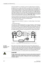
If the earth current differential protection is used on a transformer, a comparative test
is performed (see Figure 3-26). Measured value 3I0-1 is allocated to side 1 and 3I0-2
to the earth current I
EE2
. The test method is similar to the one described above. For
the test current, it is essential to ensure that on the generator side the continuously
permissible unbalanced load current is not exceeded. With a wye-delta connection,
the single-phase fault is modeled on the generator side as a phase to phase fault.
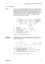
Figure 3-26
Testing the Earth Current Differential Protection on the Transformer
Test with
Secondary Test
Equipment
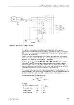
Measurements are always performed from the side with the earthed starpoint. In
transformers, there must be a delta winding (d-winding or compensating winding). The
winding not involved in the test remains open, because the delta winding automatically
provides for a low resistance of the zero sequence current path. The test arrangement
varies dependent of the application. Figures 3-27 to 3-30 show examples of test ar-
rangements, with Figure 3-27 being the preferred type for generator protection.
7UM62
DANGER!
Primary measurements must only be carried out on disconnected and earthed
equipment of the power system. Danger to life exists even on disconnected
equipment because of capacitive coupling from other energized equipment of
the power system!

