Impedance Protection (ANSI 21)
123
7UM62 Manual
C53000-G1176-C149-3
2.17.1.2 Determination of the Short–Circuit Impedance
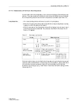
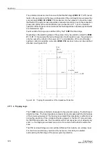
For calculation of the fault impedance, the currents and voltages of the faulty loop are
decisive. The phase selective fault detector determines the faulted loop and releases
the corresponding measurement values for impedance calculation (see Table 2-7).
Loop Selection
−
The corresponding phase-earth loop is used for a 1-pole pickup.
−
With a 2-pole pickup, the phase-phase loop with the corresponding phase-to-phase
voltage is used for impedance calculation.
−
With a 3-pole pickup, the phase-phase loop with the highest current value is used
and with equal current amplitudes, the procedure described in the lowest line of
Table 2-7 is applied.
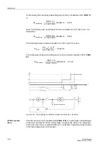
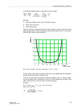
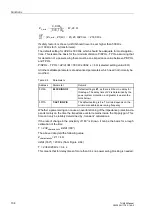
This loop selection type ensures that the fault impedance of system faults is measured
correctly via the unit transformer. A measuring error occurs with a 1-pole system short-
circuit, as the zero phase-sequence system is not transmitted via the machine
transformer (switching group e.g. Yd5). Table 2-8 describes the fault modeling and the
measuring errors.
Table 2-7
Measuring Loop Selection
Pickup
Measuring Loop
1-pole
L1
L2
L3
Phase-earth
L1–E
L2–E
L3–E
2-pole
L1...L2
L2, L3
L3, L1
Phase-phase,
Calculation of
U
I I
and
I
I I
L1– L2
L2– L3
L3– L1
3-pole, with
different amplitudes
L1.2*L2,L3
L2,2*L3,L1
L3,2*L1,L2
Phase-earth, selection of
loop with the highest current
U
I (Imax)
and
I
I (Imax)
L2–E
L3–E
L1–E
3-pole, with
same amplitude
L1, L2, L3
Phase-earth, any, maximum
current amount)
IIL1=IL2=IL3 => IL1
IL1=IL2 > IL3 => IL1
IL2=IL3 > IL1 => IL2
IL3=IL1 > IL2 => IL1

