Functions
262
7UM62 Manual
C53000-G1176-C149-3
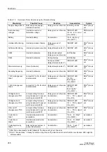
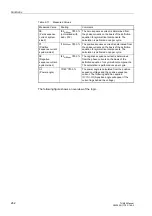
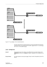
The following figure shows an overview of the logic.
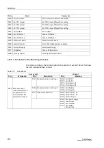
I0
(Zero sequence
current system
side 2)
I0/I
N,S2,sec
⋅
100 %
(normalized with
addr.
The zero sequence current is determined from
the phase currents on the basis of the definition
equation for symmetrical components. The
calculation is perfomed once per cycle.
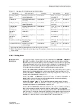
I1
(Positive
sequence current
system side 2)
I1/I
N,S2,sec
⋅
100 %
The positive sequence current is determined from
the phase currents on the basis of the definition
equation for symmetrical components. The
calculation is perfomed once per cycle.
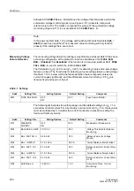
I2
(Negative
sequence current
system side 2)
I2/I
N,S2,sec
⋅
100 %
The negative sequence current is determined
from the phase currents on the basis of the
definition equation for symmetrical components.
The calculation is perfomed once per cycle.
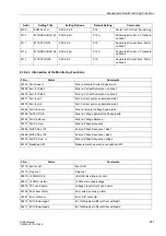
ϕ
(Power angle)
ϕ
/180°
⋅
100 %
The power angle is calculated from the positive
sequence voltage and the positive sequence
current. The following definition applies:
ϕ
=
ϕ
U -
ϕ
I (A positive angle will appear if the
current lags behind the voltage)
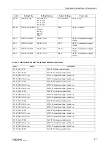
Table 2-17
Measured Values
Measured Value
Scaling
Comments

