Trip Circuit Supervision
255
7UM62 Manual
C53000-G1176-C149-3
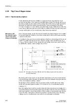
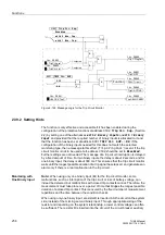
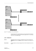
The conditions of the two binary inputs are checked periodically. A check takes place
about every 600 ms. If three consecutive conditional checks detect an abnormality
(after 1.8 s), an annunciation is reported (see Figure 2-122). This is used to avoid the
annunciation for brief transition periods. When the fault in the trip circuit has been
cleared, the annunciation is automatically reset.
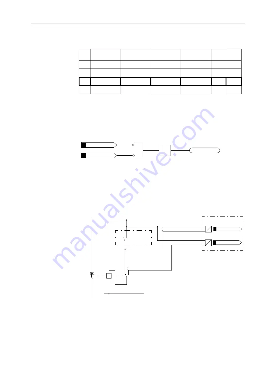
Figure 2-122 Logic Diagram for Trip Circuit Monitoring with Two Binary Inputs
Monitoring with
Two Binary Inputs
(Connected to
Common Potential)
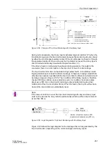
If two binary inputs connected to common potential are used, they are connected
according to 2-121, i.e. to L+ or once in parallel to the corresponding protection
command relay contact and to the CB auxiliary contact 1.
Figure 2-123 Principle of Trip Circuit Monitor with two Binary Inputs (Connected to Common
Potential)
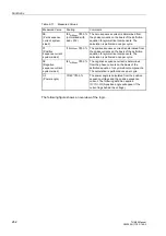
Table 2-15
Condition Table for Binary Inputs, depending on RTC and CB Position
No.
Trip Contact
Circuit
Breaker
AuxCont 1
AuxCont 2
BI 1
BI 2
1
Open
CLOSED
Closed
Open
H
L
2
Open
OPEN
Open
Closed
H
H
3
Closed
CLOSED
Closed
Open
L
L
4
Closed
OPEN
Open
Closed
L
H
&
> n
n . ..... Number of condition checks (= 3)
(measurement repeated every 600 ms)
“L”
“H”
“L”
FNo.
FNo.
FNo.
L
–
L
+
RTC
AuxCont 2
Aux
U
BI1
U
BI2
U
St
7UM62
7UM62
TC
CB
Legend:
RTC
— Relay trip contact
CB
— Circuit breaker
TC
— Circuit breaker trip coil
AuxCont1
— Circuit breaker aux. contact (NO contact)
AuxCont2
— Circuit breaker aux. contact (NC contact)
U
Ctrl
— Control voltage (trip voltage)
U
BI1
— Input voltage for 1st binary input
U
BI2
— Input voltage for 2nd binary input
Note: In the figure the circuit breaker is shown closed.
Cont 1
FNo.
FNo.

