3.3 Commissioning
353
7UM62 Manual
C53000-G1176-C149-3
= yyy
Ω
(address
correspond with the above values. Remove earth fault bridge.
An earth fault is now fitted as described above via a resistor of the warning resistance,
(
, address
, 10 k
Ω
when delivered from factory.
The earth resistance calculated by the unit can be read out under the Operational
Measured Values as
Rotor
. If substantial deviation occurs between the actual rotor
earth resistance and the indicated resistance, the accuracy can be improved by
correction of the c.t. angle error
(address
. This c.t. angle error
correction is only effective for the rotor earth fault protection function.
An earth fault is now fitted as described above via a resistor of approximately 90% of
the trip resistance (
, address
, 2 k
Ω
when delivered). The rotor earth
fault protection initiates a pick-up signal and after
(0.5 s when
delivered from factory) a trip annunciation (LED 1 and binary output 2) in both cases
this is a group indication “Device Trip”).
In the case of machines with excitation via slip rings, the above test is repeated for the
other slip ring.
Remove earth fault resistor.
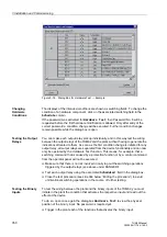
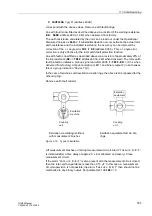
Figure 3-19
Types of Excitation
Lift measurement brushes or interrupt measurement circuit. Alarm “
is indicated after a time delay of approx. 5 s (not allocated on delivery). Close
measurement circuit.
If the alarm “
” is also present with the measurement circuit closed,
then the rotor-earth capacitance is less than 0.15 µF. In this case, a measurement
circuit supervision is not possible; the alarm “
” then should not be
marshalled to any binary output. Set parameter
= 0.
Excitation via rotating rectifiers
with measurement brushes
Excitation equipment fed via slip
rings
Excitation
equipment
Coupling
unit
Excitation
machine
Coupling
unit

