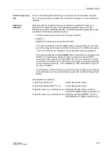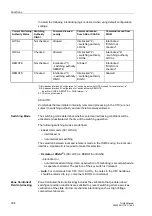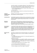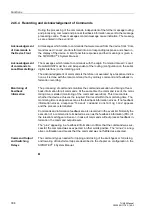
3 Installation and Commissioning
314
7UM62 Manual
C53000-G1176-C149-3
3.1.2
Connections
Overview diagrams are shown in Appendix A.2. CT and VT connections for a 7UM62
are shown in the Appendix, Section A.4. Make sure that the settings of the
Power
System Data 1
(Section 2.3) match the connections.
Currents/Voltages
Overview diagrams are shown in the Appendix. Figures and A-27 show examples of
current transformer circuit connections with busbar connection (address
=
Busbar
), Figures A-28 and A-29 with unit connection (address
=
Unit transf.
). In all examples the CT starpoints point towards the machine;
therefore, address
and
must be
set to
Yes
.
In Figures to A-28, the U
E
input of the device is connected to the open delta winding
of a voltage transformer set. Consequently, address
must be set to
=
delta winding
.
Figure is the standard connection where one busbar is fed by several generators. As
the earth fault current can be increased by an earthing transformer connected to the
busbar (approx. 10 A max.), a protection range of up to 90 % can be achieved. To
achieve the necessary sensitivity, the earth fault current is measured using a toroidal
current transformer. During startup of the machine, the displacement voltage can be
used as a criterion for detecting an earth fault until synchronization is completed.
Factor
considers the transformation ratio between the primary
and the secondary side of the summation current transformer when the sensitive
current input of side 2 in Figure is used. Likewise, factor
applies
when the input of side 1 is used.
Example:
Summation current transformer 60 A/1 A
Matching factor for sensitive earth fault current detection:
=
60
(if the input on side 2 is used)
If the sensitive current input of side 1 is used for rotor earth fault current detection (as
suggested in ),
=
1
is chosen.
In Figure A-27 the generator starpoint has a low-resistance earthing. To avoid
circulating currents (3rd harmonics) in multi-generator connections, the resistor
should be connected to only one generator. For selective earth fault detection, the
sensitive earth fault current input I
EE2
is looped into the common return line of the two
sets of CTs (current differential measurement). The current transformers are earthed
in one place only.
is set to =
1
. It is recommended to use for this type
of circuit current transformers that are balanced to one another (turns correction).
In Figure A-28 the earth fault is detected by means of the displacement voltage. A
loading resistor is provided on the broken delta winding to avoid spurious tripping in
case of earth faults occurring in the power system. The U
E
input of the device is
connected via a voltage divider to the broken delta winding of an earthing transformer
(address
=
delta winding
). Factor
0225A
is determined by the transformation ratio of the secondary-side voltages:
U
N prim.
3
--------------------
U
N sec.
3
------------------
⁄
U
N sec.
3
------------------
⁄


