Functions
126
7UM62 Manual
C53000-G1176-C149-3
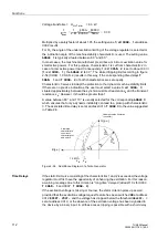
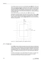
The protected zones can be chosen such that the first stage (
) covers
faults in the generator and the lower voltage side of the unit transformer, whereas the
second stage (
) measures into the network. It should be noted
that faults in the system cause impedance measurement errors due to the connection
group (star-delta) of the unit transformer (see subsection 2.17.1.2). An unwanted
operation of the stage can be excluded as the fault impedances of power system faults
are modeled too high.
Faults outside this range are switched off by the
final time stage.
Depending on the switching status of the system, it may be useful to extend the
,
. If, for example, the high-voltage side circuit breaker is open, the pickup can
only be caused by a fault in the power unit. If a consideration of the circuit breaker
auxiliary contact is possible, a so-called
overreach zone can be switched
effective (see Figure 2-62).
Figure 2-60
Tripping Characteristics of the Impedance Protection
2.17.1.4 Tripping Logic
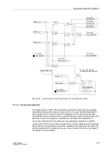
The
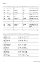
time delay is started subsequent to the protection pickup. The fault loop is
determined now. The loop impedance components are compared with the limit values
of the zones previously set. The tripping is executed if the impedance is within its zone
during the expiration of the corresponding time stage. For the first Z1 zone and also
for the Z1B overreach zone, the time delays will in most cases be zero or at least very
short, i.e. the tripping is executed as soon as it is certain that the fault is within this
zone.
The Z1B overreach stage can be switched effective from outside, via a binary input.
For the Z2 zone which may reach into the network, a time delay is selected
overreaching the first stage of the power system protection.
R1=Z1
X2=Z2
X1b=Z1b
X1=Z1
R2=Z2
R1b=Z1b
R
X

