Functions
78
7UM62 Manual
C53000-G1176-C149-3
Due to their predominantly inductive component, faults in the proximity of the
generator have relatively high short-circuit time constants that cause a magnetization
of the current transformers. The CTs should be designed accordingly (see Appendix
A.7).
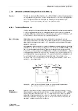
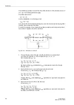
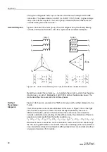
Figure 2-31
Definition of Current Direction for Longitudinal Differential Protection
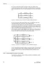
For use as a transverse differential protection, there is a particularity. Figure 2-32
shows the definition of the measuring currents for this application.
In the transverse differential protection, the phases connected in parallel constitute the
limit between the protected zone and the network. A differential current appears in this
type of circuit always if there is a current difference within the phases, and only in that
case, so that a fault current in that phase can be assumed.
Since in this case, unlike the other applications, all currents flow into the protected ob-
ject in healthy operation, a “wrong” polarity is set for one set of CTs, as described in
Section 2.3.2 under “Connection of the Current Transformer Sets“.
Figure 2-32
Definition of Current Direction for Transverse Differential Protection
The CTs also determine the limits of sensitivity in the case of motors. In asynchronous
motors, the startup operation may be modeled in different ways by the CTs, so that
major differential currents occur (see also side title ”Increase of Pickup Value on
Startup”).
2.12.1.2 Protected Object Transformer: Particularities
Transformers are subject to a number of influences that induce differential currents
even during normal operation:
L
1
L
2
L
3

