


3.1 Installation and Connections
313
7UM62 Manual
C53000-G1176-C149-3
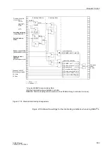
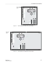
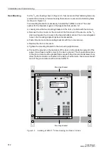
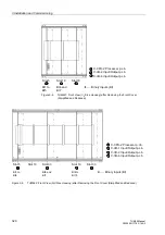
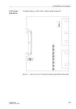
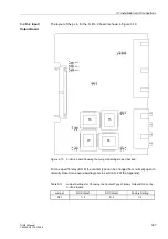
Figure 3-4
Installing a 7UM621 (
1
/
1
Size Housing) in a Rack or Cubicle
G
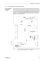
Connect the plug terminals and/or the threaded terminals on the rear side of the
device according to the elementary diagram for the rack.
When using spade lugs or directly connecting wires to threaded terminals, the
screws must be tightened so that the heads are even with the terminal block before
the lugs or wires are inserted.
A ring lug must be centered in the connection chamber so that the screw thread fits
in the hole of the lug.
SIPROTEC
®
4 System Manual has pertinent information regarding wire size, lugs,
bending radius (fiber cables), etc.
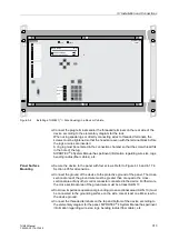
Panel Surface
Mounting
G
Secure the device to the panel with four screws. Refer to Figure 4-16 and 4-17 in
Section 4.35 for dimensions.
G
Connect the ground of the device to the protective ground of the panel. The cross-
sectional area of the ground wire must be greater than or equal to the cross-
sectional area of any other control conductor connected to the device. Furthermore,
the cross-sectional area of the ground wire must be at least AWG 13.
G
Solid, low impedance operational grounding (cross-sectional area
≥
AWG 13) must
be connected to the grounding surface on the side. Use at least one M4 screw for
the device ground.
G
Connect the threaded terminals on the top and bottom of the device according to
the elementary diagram for the panel. SIPROTEC
®
4 System Manual has pertinent
information regarding wire size, lugs, bending radius (fiber cable), etc.
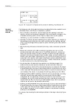
SIEMENS
SIPROTEC
1
2
6
3
+/-
0
5
4
7
8
9
7UM622
RUN
ERROR
MENU
ESC
LED
ENTER
F4
F1
F2
F3
Annunciations
Masured values
MAIN MENU 01/04
Annunciations 1
Measured values 2
Alarm


