Functions
178
7UM62 Manual
C53000-G1176-C149-3
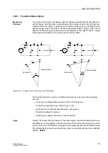
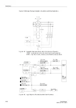
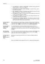
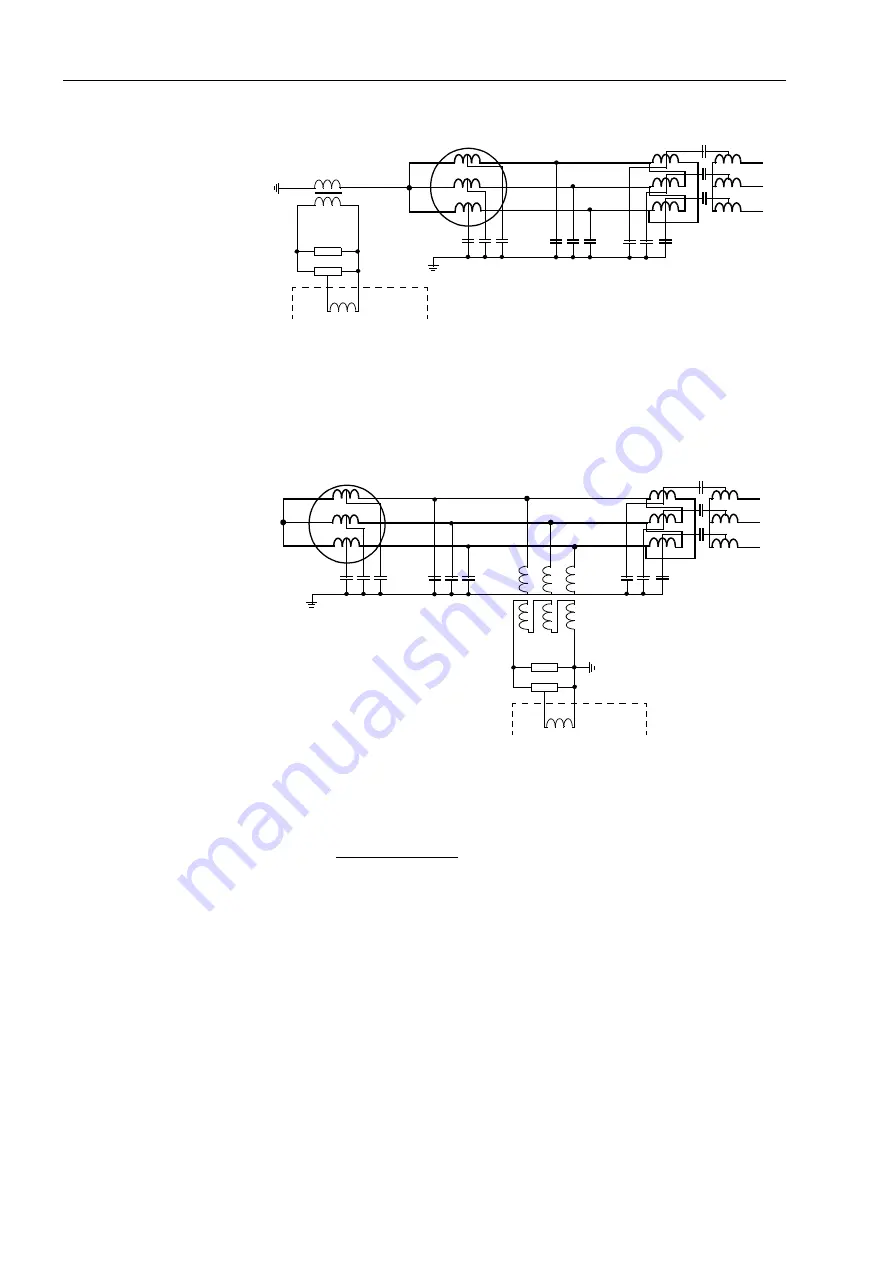
Figure 2-82
Unit Connected Generator with Neutral Earthing Transformer
Figure 2-83
Unit Connected Generator with Earthing Transformer
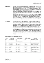
Earth Current
Direction Detection
For machines in busbar connection, it is not possible to differentiate between a
network earth fault or a machine earth fault by the displacement voltage alone. In this
case the earth fault current is used as a further criterion, and the displacement voltage
as a necessary release condition.
To achieve the necessary sensitivity, the earth fault current is measured using a
toroidal current transformer or a set of CTs in Holmgreen connection. During a
network earth fault, the machine supplies only a negligible earth fault current across
the measurement location, which must be situated between the machine and the
network. During a machine earth fault, the earth fault current of the network is
available. However, since the network conditions generally vary according to the
switching status of the network, a loading resistor, which supplies an increased earth
fault current on the occurrence of a displacement voltage, is used in order to obtain
definite measurement conditions independent of the switching status of the network.
The earth fault current produced by the loading resistor must always flow across the
measurement location.
U
E
R
B
7UM62
C
L
C
G
C
K
C
Tr
R
T
R
B
– Loading resistor
R
T
– Voltage divider
U
E
– Displacement voltage
C
G
– Generator earth capacitance
C
L
– Line earth capacitance
C
Tr
– Unit transformer earth capacitance
C
K
– Coupling capacitance of unit transformer
U
E
R
B
7UM62
R
T
C
K
C
Tr
C
L
C
G
R
B
– Loading resistor
R
T
– Voltage divider
U
E
– Displacement voltage
C
G
– Generator earth capacitance
C
L
– Line earth capacitance
C
Tr
– Unit transformer earth capacitance
C
K
– Coupling capacitance of unit

