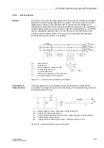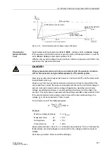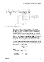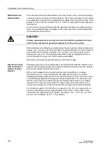
3.4 Primary Commissioning Tests with the Generator
367
7UM62 Manual
C53000-G1176-C149-3
Symmetrical
Current Test
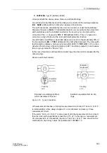
The operational measured values supplied by the 7UM62 allow a fast commissioning
without external instruments. The indices of the measured currents are defined as
follows:
The symbol for current
I
is followed by the phase identifier Lx and by the index of the
side of the protected object (e.g. the transformer winding). Example:
I
L1S1
Current in phase L1 on side 1.
Absolute Value
Measurement
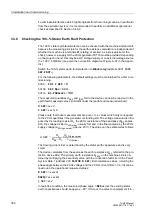
Compare the currents displayed at
Measurement
→
Secondary Values
→
Operational values, secondary
with those that are actually flowing.
I
L1S1 =
I
L2S1 =
I
L3S1 =
I
L1S2 =
I
L2S2 =
I
L3S2 =
If deviations occur that cannot be explained by measuring tolerances, either the
connection or the test arrangement is wrong:
•
Disconnect the protected object (shut down generator), and earth it,
•
Check and correct the connections and the test arrangement,
•
Repeat the test and re-check the measured values.
Angle
Measurement
If the current magnitudes are consistent, the next step is to check the phase angle
relations between the currents (
ϕ
IL1S1,
ϕ
IL2S1,
ϕ
IL3S1,
ϕ
IL1S2,
ϕ
IL2S2,
ϕ
IL3S2).
The angle differences are referred to winding L1 of side 1.
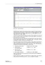
Check the angles that are output by the device for side 1 at
Measurement
→
Secondary Values
→
Angles
. All angles are referred to
I
L1 S1. Consequently, a
clockwise phase rotation should produce roughly the following results:
ϕ
L1 S1 = 0°
ϕ
L2 S1 = 240°
ϕ
L3 S1 = 120°
If the angles are not correct, wrong polarity or phase interchange at side 1 is the
cause.
•
Disconnect the protected object (shut down generator), and earth it,
•
Check and correct the connections and the test arrangement,
•
Repeat the test by renewed measurement request and re-check the measured
values.
Check the angles that are output by the device for side 2 at
Measurement
→
Secondary Values
→
Angles
. All angles are referred to
I
L1S1. If the angles are
not correct, wrong polarity or phase interchange at side 2 is the cause; proceed as for
side 1.
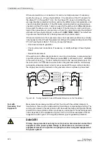
The polarities of the through-flowing currents are here defined in such a manner, that
for currents of equal phase flowing through the protected object, the angle difference
at the two measuring points is 180° between currents of the same phase, provided that
the connections are correct. Exception: Transverse differential protection, where both
currents must be in phase.
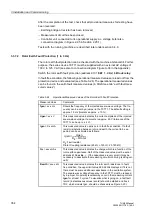
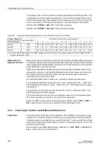
The theoretical angles depend on the protected object and – in the case of
transformers – on the vector group. They are listed in Table 3-25 for clockwise phase
rotation.

