4 Technical Data
414
7UM62 Manual
C53000-G1176-C149-3
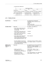
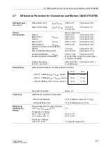
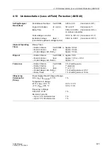
4.5
Unbalanced Load (Negative Sequence) Protection (ANSI 46)
Setting Ranges/
Resolutions
Permissible Unbalanced Load I
2
>/I
N
3.0 % to 30.0 %
(Increments 0.1 %)
(Warn. Stage too)
Tripping Stage (Definite Time)I
2
>>/I
N
10 % to 100 %
(Increments 1 %)
Delay Times
T(I
2
>), T(I
2
>>) 0.00 s to 60.00 s
(Increments 0.01 s)
or
∞
(does not expire)
Asymmetry Factor
K
2.0 s to 100.0 s
(Increments 0.1 s)
Time for Cool Down
T
Cool down
0 s to 50 000 s
(Increments 1 s)
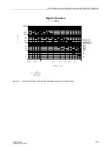
Trip Characteristic
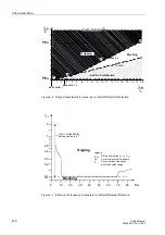
refer also to Figure 4-5
Inherent Operating
Times
Pickup Times
Warning Stage I
2
>, Tripping Stage I
2
>>
Approx. 50 ms
Dropout Times
Warning Stage I
2
>, Tripping Stage I
2
>>
Approx. 50 ms
Dropout
Warning Stage I
2
>, Tripping Stage I
2
>>
Approx. 0.95
Thermal Replica
drop-off at
I
2
<
I
2 perm.
Tolerances
Pickup Values I
2
>, I
2
>>
3 % of setting value or 0.3 % unbal. load
Delay Times T
1 % of setting value or 10 ms
Thermal Replica for 2
≤
I
2
/I
2 perm.
≤
20
5 % of reference (calculated) value + 1 %
current tolerance, or 600 ms
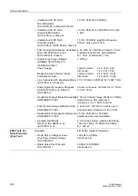
Influencing
Variables for
Pickup
Power Supply Direct Voltage in Range
0.8
≤
U
PS
/ U
PS nominal
≤
1.15
1 %
Temperature in Range
23 °F
≤ ϑ
amb
≤
131 °F
0.3 % / 10 °F
–5 °C
≤ ϑ
amb
≤
55 °C
0.5 % / 10 K
Frequency in Range
0.95
≤
f/f
N
≤
1.05
1 %
Harmonic Currents
– Up to 10 % 3rd Harmonics
1 %
– Up to 10 % 5th Harmonics
1 %
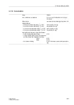
t
K
I
2
I
N
⁄
(
)
2
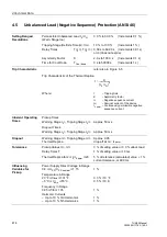
----------------------
=
Trip Characteristic of the Thermal Replica
t
– Tripping time
K
– Asymmetry factor
I
2
– Negative sequence current
I
N
– Nominal current of the device
I
2 perm.
– Continuously permissible negative
sequence current
Where:


