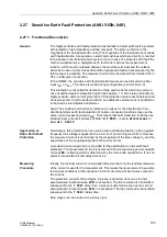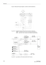
100–%–Stator Earth Fault Protection with 3rd Harmonics (ANSI 27/59TN 3rd Harm.)
191
7UM62 Manual
C53000-G1176-C149-3
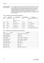
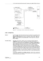
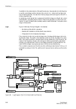
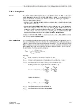
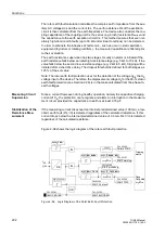
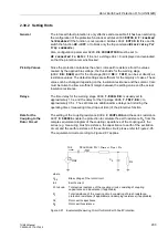
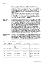
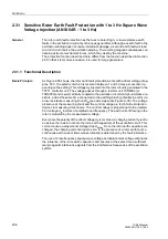
Figure 2-91
Logic Diagram of the 100–%–Stator Earth Fault Protection
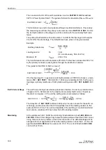
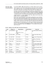
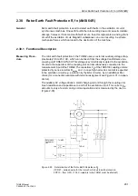
2.28.2 Setting Hints
General
The 100 % stator earth fault protective function is only effective and available if
0152
has been set during the configuration of the protective functions to
Enabled
. Set
Disabled
if the function is not required. Address
is used to switch the function
ON
or
OFF
, or to block only the trip command
(
Block Relay
).
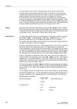
Connection Type
Depending on the system conditions, the user specified at address
during the project configuration if the displacement voltage U
en
is
tapped via a neutral transformer (
Ue connected to neutral transformer
) or
via the broken delta winding of an earthing transformer (
Ue connected to broken
delta winding
) and fed to the protective relay. If it is possible to make the
displacement voltage available to the protective relay as a measured quantity,
calculated quantities are used and the parameter must be set to
not connected
.
The option
UE connected to any VT
is selected if the 7UM62 voltage input shall
be used for measuring any other voltage instead of using it for earth fault protection.
In this case the function 100–%–stator earth fault protection is blocked. The option
Ue
connected to Rotor
is selected if the bias voltage for rotor earth fault connection
shall be fed in at this input. In this case the function 100–%–stator earth fault protection
is blocked.
The option
Ue connected to loading resistor
is for the 100–%–stator earth
fault protection with 20–Hz–injection. At this setting the 100–%–stator earth fault pro-
tection with 3rd harmonics is blocked.
broken delta winding
FNo. 05567
&
Tripping
matrix
FNo. 05568
&
FNo. 05553
FNo. 05562
U(3.H.)
not connected
or
broken delta winding
neutral transformer
Neutral transformer
not connected
connected to any VT
”1”
connected to Rotor
TMin
TRIP CMD
Load Resistor


