Sensitive Rotor Earth Fault Protection with 1 to 3 Hz Square Wave Voltage Injection (ANSI 64R - 1 to 3 Hz)
211
7UM62 Manual
C53000-G1176-C149-3
2.31.2 Setting Hints
General
The sensitive rotor earth fault protection is only effective and accessible if it has been
set to
at address 0161
during the configuration of the protection
functions.
It must also be ensured that the measuring transducer inputs TD1 and TD2 are not
used for any other function.
Address
is used to switch the function ON or OFF, or to block only
the trip command (Block relay).
Pickup Values
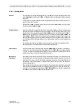
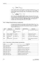
Since the protection calculates the ohmic rotor-earth resistance from the values sup-
plied by the injected voltage, the series resistance and the flowing earth current, the
thresholds for the warning stage
) and for the trip stage (
) can be set directly as resistance values. The default settings (
= 40
k
Ω
and
= 5 k
Ω
) are sufficient for the majority of cases. These values can
be changed depending on the insulation resistance and the coolant. Care must be tak-
en to allow a sufficient margin between the setting value and the actual insulation re-
sistance.
As interference from the excitation system cannot be excluded, the setting for the
warning stage is not finally determined until the primary tests.
Time Delays
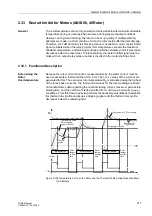
The time delay for the warning stage (
) is usually set to approxi-
mately 10 s, and the delay for the trip stage (
) to approximately
1 s. The set times are additional time delays not including the operating times (mea-
suring time, drop-out time) of the protection function.
Monitoring
Functions
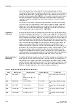
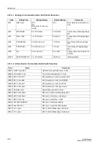
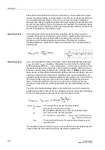
The setting value of the measuring circuit monitoring (
) is defined during
the primary tests. For this purpose, the operational measured value (Qc) is read out,
and half of the value is set. If the charge measured is too low, the monitoring cannot
be effective. The parameter
should in that case be set to 0 mAs. No fault indi-
cation will be issued.
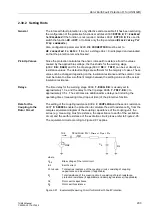
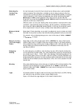
No settings are required if you want to perform the external test using the test resistor
included in the 7XR6004 (3.3 k
Ω
). If a different resistor is to be used, its resistance
must be set in the advanced parameter
(can only be changed with
the DIGSI communication software) at address
.

