Auxiliary Functions
293
7UM62 Manual
C53000-G1176-C149-3
i
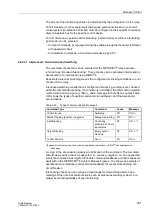
L1 S1
; i
L2 S1
; i
L3 S1
; i
EE1
; i
L1 S2
; i
L2 S2
; i
L3 S2
; i
EE2
and u
L1
, u
L2
, u
L3
, u
E
and
u
=
or i
=
of the three measuring transducers
are sampled at intervals of 1.25 ms (for 50 Hz) or 1.04 ms (for 60 Hz), and stored in a
circulating buffer (16 samples per cycle). For a fault, the data are stored for an
adjustable period of time, but not more than 5 seconds.
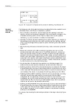
The r.m.s. values of the measured quantities
I
1
, I
2
, I
EE2
, I
EE1
; U
1
, U
E
, P, Q,
ϕ
, f–f
N
, R and X can be stored in a circulating buffer,
in a grid of 1 measured value per cycle. R and X are the positive sequence
impedances. For a fault, the data are stored for an adjustable period of time, but not
more than 80 seconds.
Up to 8 fault records can be recorded in this buffer. The memory is automatically
updated with every new fault, so no acknowledgment for previously recorded faults is
required. Waveform capture can also be started with protection pickup, via binary
input, via operator interface, or SCADA.
The data can be retrieved via the serial interfaces by means of a personal computer
and evaluated with the protection data processing program DIGSI
®
4 and the graphic
analysis software SIGRA
®
4. The latter graphically represents the data recorded
during the system fault and calculates additional information such as the impedance
or RMS values from the measured values. A selection may be made as to whether the
currents and voltages are represented as primary or secondary values. Binary signal
traces (marks) of particular events e.g. ”fault detection”, ”tripping” are also
represented.
If the device has a serial system interface, the fault recording data can be passed on
to a central device via this interface. The evaluation of the data is done by applicable
programs in the central device. Currents and voltages are referred to their maximum
values, scaled to their rated values and prepared for graphic representation. Binary
signal traces (marks) of particular events e.g. ”fault detection”, ”tripping” are also
represented.
In the event of transfer to a central device, the request for data transfer can be
executed automatically and can be selected to take place after each fault detection by
the protection, or only after a trip.
2.45.4 Date and Time Stamping
Integrated date and time stamping allows for the exact evaluation of sequence of
events (e.g. operations or error messages, or limit violations). The clock may be
influenced by:
•
the internal RTC clock (Real Time Clock),
•
external synchronization sources (DCF, IRIG B, SyncBox, IEC 60870–5–103,
PROFIBUS),
•
external minute impulses via a binary input.
Note:
The device is delivered from the factory with the internal RTC clock selected as the
time source, independent of whether the device is equipped with a system interface
or not. If external synchronization is desired, it must be configured accordingly.

