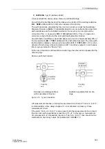
3.3 Commissioning
355
7UM62 Manual
C53000-G1176-C149-3
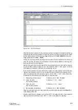
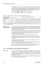
Figure 3-20
Test Fault Record
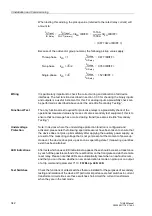
After this the fault resistors for the warning and the trip stage are installed, and the op-
erational measured value Rearth is read out. The two measured values are the basis
for the setting values of the warning stage (address
) and the trip
stage (address
).
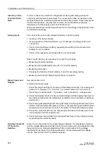
Finally, the warning and the trip stage are checked. The test resistance for this is ap-
prox. 90 % of the set value. On generators or motors with excitation by sliprings, the
test is performed for both sliprings.
Remove the earth fault resistor and lift the measuring brushes or interrupt the measur-
ing circuit. After a delay of approx. 10 s, the indication „
“ is issued
(not masked on delivery). Re-close the measuring circuit.
If you want to perform an automatic test by means of a test resistor, this mechanism
needs to be tested as well. To do so, connect the test resistor at the slipring to the
earth, and activate the test via binary input („
“). Next, check the
indications for the following four test steps to be performed.
1.
Measuring circuits closed
Indication „
2.
Open circuit at
Indication „
1st coupling resistor
3.
Open circuit at
Indication „
2nd coupling resistor
4.
Re-establish connections
Indication „
Stop the automatic test and check again the operational measured value Rearth. It
must display 999.9 k
Ω
.
Finally, switch the AC voltage source of the 7XT71 off. After about 5 s, the protection
device issues the indication „
“ (not masked on delivery).


