3.1 Installation and Connections
327
7UM62 Manual
C53000-G1176-C149-3
C–I/O–2 Input/
Output Board
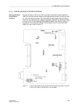
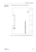
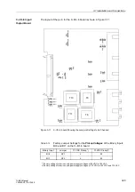
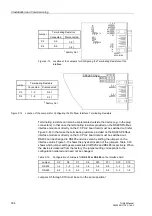
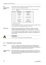
The layout of the p.c.b for the C–I/O–2 board is shown in Figure 3-10.
Figure 3-10
C–I/O–2 board Showing the Jumpers Settings to be Checked
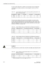
For one specific relay (BO 6) the contact type can be changed from normally open to
normally closed (see overview diagrams in section A.2 of the Appendix):
Table 3-10
Jumper Settings for Choosing the Contact Type of Binary Output BO 6 on the
C–I/O–2 Board
Jumper
NO Contact
NC Contact
Factory Setting
X41
1–2
2–3
1–2
X6
1
1A
5A
3
2
1
T8
T6
T7
T5
X6
4
1A
5A
3
2
1
X6
3
5A
1A
1
2
3
X62
5A
1A
1
2
3
X60
1A
5A
3
2
1
X41
1
3
2
(AD0)
L
X71
1
2
3
(AD1)
X7
2
1
2
3
(AD2)
X7
3
H

