Functions
102
7UM62 Manual
C53000-G1176-C149-3
•
Phase current monitoring
To preclude spurious tripping due to CT saturation in the presence of external
faults, the protection function is blocked as soon as a maximum phase current is
reached. To do so, the phase currents of side 1 are monitored. As soon as one
phase current exceeds the threshold, the blocking takes effect.
This blocking is no drawback, since high-current faults are sufficiently controlled by
other protection functions such as differential protection, impedance protection and
overcurrent protection.
•
Zero voltage monitoring
Where the phase current transformers model zero sequence currents on the sec-
ondary side after loads have been switched in, and where there is no direct evalu-
ation of the starpoint current, zero voltage monitoring should be used. It also pro-
vides additional restraint in the presence of external faults without earth involve-
ment.
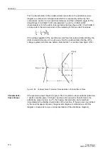
The zero voltage is calculated from the phase-to-earth voltages. On detection of a
zero voltage, a release signal is output.
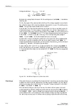
Logic
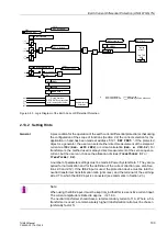
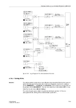
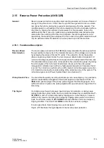
The logic interconnection of all signals and the most important settings, as well as the
indications output, are shown in Figure 2-50. The function can be blocked with the in-
put “
”. This input also allows to block other features using the CFC, for
instance if the measured zero voltage is to be injected via the U
E
input. This is neces-
sary if the voltage inputs are connected to a voltage transformer in V connection (open
delta connection).
Figure 2-50 shows the blocking of the phase currents and their release on the basis
of the calculated zero voltage. This is followed by the monitoring of the operating char-
acteristic with possibly an additional query of the starpoint current, and the angle re-
lease. When all conditions are met, the earth current differential protection picks up.
The subsequent timer
is usually set to zero.


