Earth Current Differential Protection (ANSI 87GN, TN)
103
7UM62 Manual
C53000-G1176-C149-3
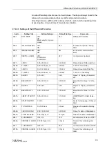
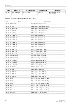
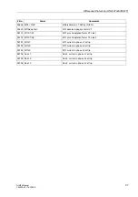
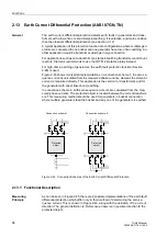
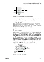
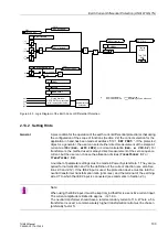
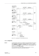
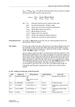
Figure 2-50 Logic Diagram of the Earth Current Differential Protection
2.13.2 Setting Hints
General
A precondition for the operation of the earth current differential protection is that during
the configuration of the scope of functions (Section 2.2) the correct selection for the
application in hand has been made at address “
”. If the protected
object is a generator, the user can select either direct measurement of the starpoint
current via IEE2 (
), or current calculation (
). For
transformers, the method used is always direct measurement of the zero sequence
current, but the user can choose the allocation of sides (
or
A number of parameter settings must be made in Power System Data 1. They are re-
quired for normalization and for the definition of the current direction (see also Sec-
tions 2.3 and 2.12). If the IEE2 input is used, the protection device must be told the
neutral transformer transformation ratio (prim./sec.) and the terminal of the earthing-
side CT to which the IEE2 input is connected (see comments in Section 2.3).
>BLOCK REF
5803
2102 REF I> BLOCK
2103 REF U0>RELEASE
5812
REF BLOCKED
5840
REF I> blocked
5841
REF U0> releas.
2110 I-REF>
2113 SLOPE
2114 BASE POINT
5817
REF picked up
2112 T I-REF>
5821
REF TRIP
OR
OR
&
Pickup decision,
DIFF/RESTR characteristic
with I
02
threshold criterion
Angle difference
evaluation
&
I
L1Sm
I
L2Sm
I
L3Sm
U
0
"1"
I
0DIFF
I
0RES
I
02
|
∆ϕ
|
1.0...100.0 V
0.0 V
Tripping
matrix
Tmin TRIP
CMD
1)
1)
1)
1)
Use in generators:
I
LxSm
always side 1
Use in transformers:
I
LxSm
depending on side allocation
Note:
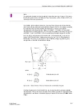
When using the IEE2 input, it must be kept in mind that this is a sensitive current input.
The current amplitude is limited to approx.
√
2 1.6 A.
The neutral transformer should have a rated secondary current of 1 A. Where a 5 A
transformer is used, a commensurately higher transformation ratio must be chosen
(preferably factor 5).

