3.4 Primary Commissioning Tests with the Generator
369
7UM62 Manual
C53000-G1176-C149-3
Primary tests of power units are performed with the generator itself. On transformers,
a low-voltage test source is used.
Before the test, the CT connections have to be visually checked for correctness.
Note:
When performing the short-circuit test (3-phase short-circuit) for the earth current dif-
ferential protection, check that the three current transformers (side 1 or side 2 – which-
ever side is used for the earth current differential protection) are identical in design. To
do so, read out the percentages of the operational measured values 3I0-1 and 3I0-2
(in DIGSI in the differential protection measured values). If the CTs are correctly
matched, the values must be zero. Values that are not zero must be taken into account
for the protection settings.
Primary Test with
Generator
This test is performed in addition to the current test. The protection must be set to max-
imum sensitivity. The zero voltage release must be blocked (address
= 0).
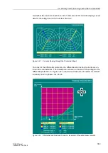
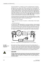
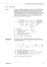
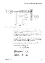
For the test, one phase is earthed and the generator is excited (see Figure 3-25). The
test current must not exceed the permissible negative-sequence current. If this current
amounts e.g. to I
2perm.
= 10 % I
N,G
, the test current must be less than 30 % I
N,G
. On
the other hand, the current is determined by the low-resistance starpoint earthing.
10 % of the rated generator current are sufficient for testing.
Figure 3-25
Testing the Earth Current Differential Protection on the Generator
For the external fault, read out the percentages of the operational measured values
(on the device: Measured values
→
I -Diff,I-Stab):
Both zero sequence currents 3I0-1 and 3I0-2 must be equal, and correspond to the
current fed in. The differential current I0-Diff is nearly zero. The restraint (stabilizing)
current I0-Stab is twice the flowing current. If the differential and the restraint current
are equal, the polarity of one CT must be wrong. This can also be seen from the phase
angle EDS |
∆Φ
| shown on the device in the phase angles, or in DIGSI. 0° means an
internal fault, and 180° an external fault. Minor deviations are caused by CT errors.
3I0–1
Calculated zero sequence current of side 1
3I0–2
Calculated zero sequence current of side 2 or measured earth current
IEE2 (depending on configuration)
I0–Diff
Calculated differential current
I0–Stab
Calculated restraint (stabilizing) current
7UM62
either connection possible

