Functions
110
7UM62 Manual
C53000-G1176-C149-3
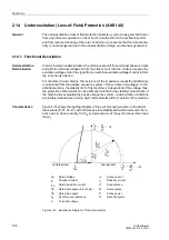
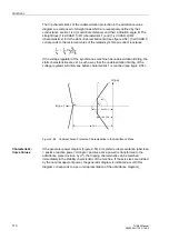
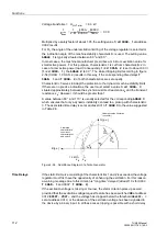
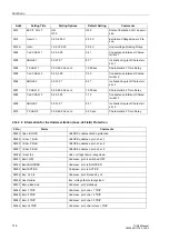
The trip characteristics of the underexcitation protection in the admittance value
diagram are composed of straight lines which are respectively defined by their
conductance section 1/xd (=coordinate distance) and their inclination angle
α
. The
straight lines (1/xd CHAR.1)/
α
1 (characteristic 1) and (1/xd CHAR.2)/
α
2
(characteristic 2) form the static underexcitation limit (see figure 2-54). (1/xd CHAR.1)
corresponds to the reciprocal value of the related synchronous direct reactance.
If the voltage regulator of the synchronous machine has underexcitation limiting, the
static characteristics are set in such a way that the underexcitation limiting of the
voltage regulator will intervene before characteristic 1 is reached (see figure 2-56).
Figure 2-54
Underexcitation Protection Characteristics in the Admittance Plane
Characteristic-
Curve Values
If the generator power diagram (Figure 2-55) in its preferred representation (abscissa
= positive reactive power; ordinate = positive active power) is transformed to the
admittance plane (division by U
2
), the tripping characteristic can be matched
immediately to the stability characteristic of the machine. If the axis sizes are divided
by the nominal apparent power, the generator diagram is indicated per unit (this
diagram corresponds to a per unit representation of the admittance diagram).
1
x
d
-----
1
X
d
------
U
N
3 I
N
⋅
-----------------
⋅
=
λ
3
λ
2
α
3
α
2
α
1
1
2
3
1/xd CH.1
1/xd CH.2
λ
2
1/xd CH.3
G [p.u.]
B [p.u.]

