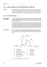
Underexcitation (Loss-of-Field) Protection (ANSI 40)
111
7UM62 Manual
C53000-G1176-C149-3
.
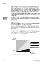
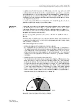
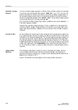
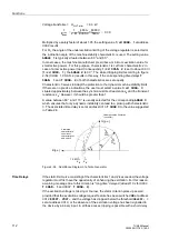
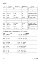
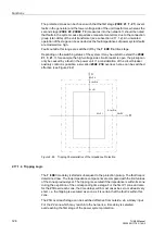
Figure 2-55
Power Diagram of a Salient-Pole Generator, Indicated per Unit
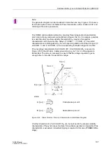
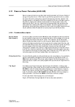
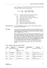
The primary setting values can be read out directly from the diagram. The related
values must be converted for the protection setting. The same conversion formula can
be used if the protection setting is calculated with the predefined synchronous direct
reactance.
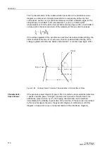
with
x
dsec
Secondary per unit synchronous direct reactance,
x
d mach
Per unit synchronous direct reactance of machine,
I
N mach
Rated machine current
U
N mach
Rated machine voltage
U
N VT prim
Primary rated voltage of the voltage transformers
I
N CT prim
Primary rated current of the current transformers
Instead of 1/x
d mach
the approximate value
I
K0
/
I
N
can be used (with
I
K0
= short-circuit
current at no-load excitation).
Setting example:
Machine:
U
N mach
= 6.3 kV
I
N mach
= S
N
/
√
3 U
N
= 5270 kVA/
√
3
⋅
6.3 kV = 483 A
x
d mach
= 2.47 (= machine manufacturer’s indication
in Fig. 2-55)
Current transformers:
I
N CT prim
= 500 A
0
0,2
0,4
0,6
0,8
1,0
1,2
1,4
–0,2
0
0,2
0,4
0,6
0,8
P/S
N
Q/S
N
Limit of the stator
winding heating
Limit of the stator
winding heating
overexcited
Measuring point
Phase
angle
–0,4
–0,6
–0,8
underexcited
U = U
N
= 6300 V
I
=
I
N
S
N
= 5270 kVA
f
N
= 50.0 Hz
n
N
= 1500 RPM
cos
ϕ
= 0.800
x
d
= 2.470
x
q
= 1.400
”Response
circle”
1
x
dsec
-------------
1
x
dmach
-----------------
I
Nmach
U
Nmach
-------------------
U
N VT prim
I
N CT prim
--------------------------
⋅
⋅
=

