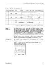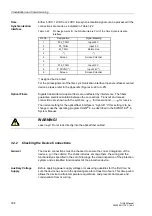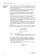
3.2 Checking Connections and System (Plant) Integration
343
7UM62 Manual
C53000-G1176-C149-3
3.2.3
Checking the Integration in the Plant
3.2.3.1
General Hints
This test is performed to ensure that the protective device is correctly integrated into
the plant to be protected.
One important step in the test is the check of the protection configuration (masking and
setting values) for conformity with the plant requirements.
An integration test across all interfaces allows to check on one hand the cubicle wiring
and the functionality in accordance with the set of drawings, and on the other hand the
correct wiring between the sensor or transformer and the protective device.
This test does not undertake to check the individual protection functions for the
accuracy of their pick-up values and characteristic curves.
Auxiliary Voltage
Supply
Check the voltage magnitude and polarity at the input terminals.
Visual Inspection
−
Check the cubicle and the devices for damage;
−
Check the earthing of the cubicle and of the protective device;
−
Check the external cabling for condition and completeness.
Warning!
The following procedures are carried out with dangerous voltages present. Therefore,
only qualified people who are familiar with and adhere to the safety procedures and
precautionary measures shall perform the procedures.
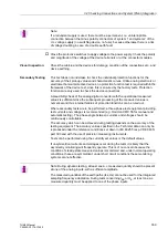
Note:
If a redundant supply is used, there must be a permanent, i.e. uninterruptible
connection between the minus polarity connectors of system 1 and system 2 of the
d.c. voltage supply (no switching device, no fuse), because otherwise there is a risk
of voltage doubling in case of a double earth fault.
Caution!
Operating the device on a battery charger without a connected battery can lead to
unusually high voltages and consequently, the destruction of the device. For limit
values see Sub-section 4.1.2 under Technical Data.

