Functions
148
7UM62 Manual
C53000-G1176-C149-3
2.19
Undervoltage Protection (ANSI 27)
General
Undervoltage protection detects and reports abnormally low voltage conditions, some
of which could be related to system stability problems (voltage collapse, etc.).
Two-pole short circuits or earth faults cause an asymmetrical voltage collapse.
Compared with three monophase measuring systems, the detection of the positive
phase-sequence system is not influenced by these procedures and is advantageous
especially with regard to the judgement of stability problems.
2.19.1 Functional Description
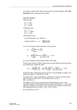
For this, the fundamental wave of the positive sequence system is paramount. The
phase voltages are filtered by the protection (Fourier analysis) and only the
fundamental waves are evaluated. Of these, the protection only detects the positive
sequence system.
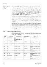
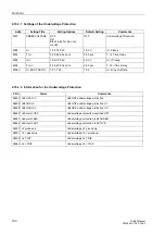
Undervoltage protection consists of two definite time elements. A pickup is signalled
as soon as the value falls below the selectable voltage thresholds. A trip signal is
transmitted if a voltage pickup exists for a selectable time.
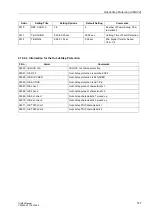
In order to ensure that the protection does not accidentally pick up due to a secondary
voltage failure, each stage can be blocked individually or both stages can be blocked
in common via binary input(s), e.g. by a voltage transformer miniature circuit breaker
(m.c.b.). In addition to this, the integrated Fuse–Failure–Monitor blocks both stages
(see section 2.38.1.4).
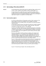
When the undervoltage protection has picked up while the relay changes to the
operational condition 0 - i.e. no suitable measured quantities are present or the
permissible frequency range has been left - pick-up will be sealed in. Thus, trip is
ensured even after the voltages have completely collapsed. This seal-in can be
cancelled only after the voltage has reverted to a value above the undervoltage drop-
off value or by activating the blocking input for undervoltage protection.
There is no pickup and trip if no pickup exists before the device is in operating status
0 (thus e.g. upon switchon of the device without present measuring quantities). An
immediate tripping may be caused on transition into operating status 1 (i.e. by
applying measuring quantities). For this reason, it is recommended to activate the
blocking input of the undervoltage protection via the circuit breaker auxiliary contact
and to block the protective function in this way, e.g. after a protection tripping.
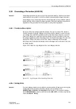
Figure 2-71 shows the logic diagram of the undervoltage protection.

