


Functions
108
7UM62 Manual
C53000-G1176-C149-3
Excitation Voltage
Request
In case of a faulty voltage regulator or a failure of the excitation voltage, it is possible
to switch up with a short delay (time stage
, e.g. 1.5 s). To do so, the
device must either be informed via a binary input of the excitation voltage failure, or
the excitation voltage must be fed in via measuring transducer TD3 and a voltage
divider, provided that at address
the excitation voltage request
via measuring transducer has been switched
ON
.
As soon as the excitation voltage drops below a settable minimum
short-time tripping is initiated.
Instead of the excitation voltage detection, or even in addition to it, the signal of an
external excitation voltage monitoring feature can be fed in via a binary input. Here
again, high-speed tripping is initiated as soon as a failure of the excitation voltage is
signalled.
Low-Pass Filter
As the excitation DC voltage may contain a large amount of superimposed harmonics
(e.g. owing to thyristor control), an analog low pass is provided on the C-I/O-6 board
in addition to the integrated digital filter. This low pass damps especially multiples of
the sampling frequency, which cannot be suppressed sufficiently by the digital filter.
The jumper settings for activating this filter are described in Section 3.1.3. When the
7UM62 is delivered from the factory, the filter is on. The jumper setting must match the
setting of the parameter
(see Power System Data, Section
2.3.2). If they do not match, an alarm is output, the device is reported faulty and not
operative.
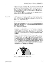
Undervoltage
Blocking
The admittance calculation requires a minimum measurement voltage. During a
severe collapse (short-circuit) or failure of the stator voltages, the protection is
therefore blocked by an integrated a.c. voltage monitor whose pickup threshold
Umin is set on delivery to 25 V.
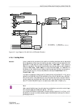
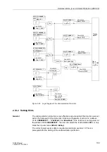
Figure 2-53 illustrates the logic diagram of the underexcitation protection.


