3 Installation and Commissioning
318
7UM62 Manual
C53000-G1176-C149-3
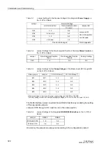
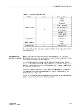
For measuring transducer TD 3 (detects e.g. the excitation voltage for the
underexcitation protection) an analog low-pass can be activated or deactivated; the
choice is made by jumpers. For more information see Table 3-16 in Section 3.1.3.3
under the side title “C–I/O–6 Input/Output Board“.
Exchanging
Interfaces
The serial interfaces can only be exchanged in the versions for panel flush mounting
and cubicle mounting. Which interfaces can be exchanged, and how this is done, is
described in Section 3.1.3.4 under the side title “Exchanging Interface Modules“.
Terminating
Resistors for
RS485 and Profibus
DP (Electrical)
For reliable data transmission, an RS 485 bus or the electrical Profibus DP should be
terminated with resistors at the last device on the bus. The printed circuit boards
(p.c.b.) of the C–CPU–2 processor module and of the RS485 or Profibus interface
module are equipped for this purpose with terminating resistors that are switched in
by means of jumpers. Only one of the three possibilities may be used. The physical
location of the jumpers on the p.c.b. is described in Section 3.1.3.3 under the side title
“Processor Printed Circuit Board C–CPU–2“ for the C–CPU–2 processor module, and
in Section 3.1.3.4 under the side title “Serial Interfaces with Bus Capability“ for the
interface modules. Both jumpers must always have the same setting.
As delivered from the factory, the resistors are switched out.
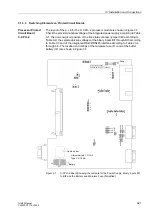
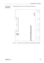
Spare Parts
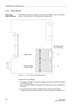
Spare parts can be the battery that provides for storage of the data in the battery-
buffered RAM in case of a power failure, and the miniature fuse of the internal power
supply. Their physical location is shown in Figure 3-7. The ratings of the fuse are
printed on the board next to the fuse itself. When exchanging the fuse, please observe
the hints given in the SIPROTEC
®
4 System Manual in the chapter “Maintenance”.
3.1.3.2
Disassembling the Device
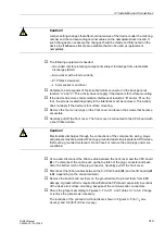
Important!
It is assumed for the following steps that the device is not operative.
To perform work on the printed circuit boards, such as checking or moving switching
elements or exchanging modules, the buffer battery or the miniature fuse, proceed as
follows:
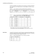
Caution!
If the jumpers are set to “current” input, connection of a voltage may destroy the board!
Note:
The jumper settings must correspond to the mode set at addresses
(volt-
age or current input) and
(with/without filter). If they do not, the device is blocked
and outputs an alarm.

