


3.3 Commissioning
357
7UM62 Manual
C53000-G1176-C149-3
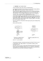
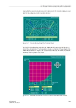
90° must be determined and set as
= –
90
° –
ϕ
SES
. If the value displayed
is, for example,
ϕ
SES
= –
75
°,
= –
15
° must be set at address
. This
will change the measured value to approx. –90°.
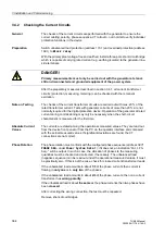
The value displayed for
R SEF
must be in fault-free condition the maximum possible
value of 9999
Ω
. The maximum value for the primary earth resistance
R SEFp
de-
pends on the selected conversion factor (
address
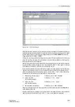
Switch off the voltage supply for the 20 Hz generator, or block the binary input. The
indication „
“ will appear (not masked on delivery). This proves that a
failure of the 20 Hz generator is reliably detected. If this indication appears already
with the 20 Hz generator in operation, the monitoring threshold (address
) should be reduced. This can be the case if the loading resistance is very small
(< 1
Ω
).
Now a variable resistor is inserted as earth resistance e.g. between generator star-
point and earth.
Set the primary earth resistance to 0
Ω
(short-circuit) and read out the operational
measured value
R SEF
. This value must be nearly zero. If the transfer resistance of
the earthing or neutral transformer is not negligible, it can be compensated. To do so,
set the measured value
R SES
at address
as
SEF Rps
.
Then the pickup value for the trip stage is specified. Set the primary earth resistance
to the tripping value (e.g. 2 k
Ω
) and read out the measured value
R SEF
. In case of
major deviations between fault resistance and measured value, the correction angle
, address
, should be slightly modified for a better match. You can
also use for this the operational measured value
PHI SEF
. It may also be necessary
to slightly change SEF Rps.
Finally, the fault resistance is read out, and set as the tripping value at address
Now the primary-side earth resistor for the alarm stage (e.g. 5 k
Ω
) is inserted, and the
fault resistance (
R SEF
) is read out. This value must be set at address
as
For the settings, only secondary values should be used. If you find during the conver-
sion from secondary to primary values that the theoretical conversion factor is not
quite correct,
should be modified to match the measuring results (for
conversion formulae refer to Section 2.29.2).
Finally, a series of measurements is performed, starting with 0 k
Ω
and proceeding in
steps of 1 k
Ω
. If changes are made to the correction angle (
address
or to the contact resistance (
, address
), the settings for the trip stage
(
) must be matched as required.
Now the earth resistance is reduced to about 90 % of the resistance for the alarm
stage (address
). After the delay time
set at ad-
dress
(10 s on delivery), the stator earth fault protection issues an alarm
„
“ (not masced on delivery).
Further reduce the earth resistance to 90 % of what the trip stage pickup value would
be for the protection device side (
, address
). The protection is-
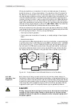
DANGER!
Hazardous voltages can be present in the generator even at stand-still. If the ex-
ternal 20 Hz bias voltage of the stator winding is switched on, it amounts to ap-
prox. 1 % to 3 % of the primary rated voltage of the generator to be protected!


