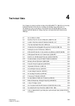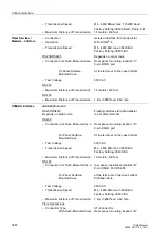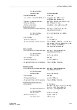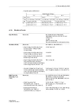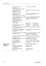
4.1 General Device Data
397
7UM62 Manual
C53000-G1176-C149-3
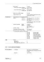
Binary inputs:
2 ranges
– For Nominal Voltages 24/48/60/
U
PU
≥
19 VDC
110/125 VDC
U
DO
≤
14 VDC
– For Nominal Voltages 110/125/
U
PU
≥
88 VDC
220/250 VDC
U
DO
≤
66 VDC
Maximum Permissible Voltage
300 VDC
Impulse Filter on Input
220 nF Coupling Capacitor at 220 V with
recovery time > 60 ms
Output Relays
1
)
Output Relays for Commands/Annunciations
Number
7UM621
∗
–
12 (1 NO contact each, 3 optionally as
NC contacts)
7UM622
∗
–
20 (1 NO contact each, 4 optionally as
NC contacts)
1 Alarm relay (NC contact or NO contact,
switch selectable)
Switching Capability
MAKE
1000W/VA
BREAK
30 W/VA
40 W resistive
25 W at L/R
≤
50 ms
Switching Voltage
250 V
Permissible Current per Contact
5 A continuous
and Total Current on Common path
30 A for 0.5 s
1
) UL–listed with the following nominal value:
120 VAC
Pilot duty, B300
240 VAC
Pilot duty, B300
240 VAC
5 A General Purpose
24 VDC
5 A General Purpose
48 VDC
0.8 A General Purpose
240 VDC
0.1 A General Purpose
120 VAC
1/6 hp (4.4 FLA)
240 VAC
1/2 hp (4.9 FLA)
LEDs
Number
RUN (green)
1
ERROR (red)
1
User-programmable LEDs (red)
14
4.1.4
Communications Interfaces
PC Front Interface
– Connection
Front panel, non-isolated, RS 232,
9-pin DSUB port for connecting a personal
computer
– Operation
with DIGSI
®
4

