3 Installation and Commissioning
316
7UM62 Manual
C53000-G1176-C149-3
Changing Setting
Groups with Binary
Inputs
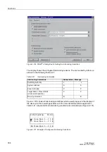
If binary inputs are used to switch setting groups, please observe the following:
•
If the configuration is performed from the operator panel or using DIGSI
®
4, the
address
must be set to the option
Binary Input
.
•
One binary input must be dedicated for the purpose of changing setting groups
when two groups are to be switched. This input is named “
>Set Group Bit 0
”.
•
The logical binary input must be allocated to a physical input module in order to
allow control. An input is treated as not energized when it is not assigned to any
physical input.
•
If the binary input is configured as a make circuit, i.e. as active when voltage is
applied (H active), the setting groups are assigned as follows:
– not energized:
Setting group A
– energized:
Setting group B
•
The status of the signal controlling the binary input to activate a particular setting
group must remain constant as long as that particular group is to remain active.
Trip Circuit
Monitoring
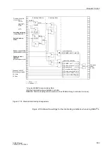
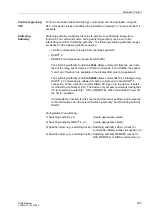
A circuit with two binary inputs (see Figure 2-121) is recommended for trip circuit
monitoring. The binary inputs must have no common potential, and their operating
point must be sensible less than half the rating of the DC control voltage.
When using only one binary input, a resistor R is inserted into the circuit on the system
side, instead of the missing second binary input (see Figure 2-124). Please note that
the response times are as long as approx. 300 s. Section 2.39.2 shows how the
resistance is calculated.
3.1.3
Hardware Modifications
3.1.3.1
General
Hardware adjustments might be necessary or desired. For example, a change of the
pickup threshold for some of the binary inputs might be advantageous in certain
applications. Terminating resistors might be required for the communication bus. In
either case, hardware modifications are needed. The modifications are done with
jumpers on the printed circuit boards inside the 7UM62. The hints given in Sections
3.1.3.2 to 3.1.3.5 should be observed in any case whenever hardware modifications
are made.
Power Supply
Voltage
There are different ranges for the input voltage of the various power supplies. Refer to
the data for the 7UM62 ordering numbers in Section A.1 of the Appendix. The power
supplies with the ratings [60/110/125 VDC] and [110/125/220/250 VDC 115 VAC] are
interchangeable. Four jumper settings determine the rating. The settings necessary to
convert one range to the other are provided below in Sub-section 3.1.3.3, under the
side title “Processor Printed Circuit Board C–CPU–2”. When the device is delivered,
these jumpers are set according to the name-plate sticker. Typically, these settings
are not changed.
Live Status Contact
The contacts of the live status (alarm) relay connected to terminals F3 and F4 of the
device can be either normally closed or normally open. The choice is made with the
setting of jumper X40. The appropriate setting of the jumper for the contact type
desired, and the location of the jumper on the printed circuit board, are described
below in “Processor Printed Circuit Board C–CPU–2“.

