Overexcitation (Volt/Hertz) Protection (ANSI 24)
161
7UM62 Manual
C53000-G1176-C149-3
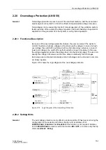
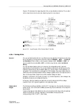
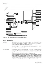
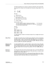
Figure 2-75 illustrates the logic diagram of the overexcitation protection. The counter
can be reset to zero by means of a blocking input or a reset input.
Figure 2-75
Logic Diagram of the Overexcitation Protection
2.22.2 Setting Hints
General
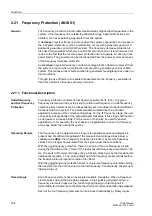
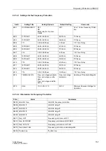
The overexcitation protection is only effective and accessible if it has been set during
the configuration of the protective functions at
=
Enabled
.
Set
Disabled
if the function is not required. Address
is
used to switch the function
ON
or
OFF
, or to block only the trip command (
Block
Relay
).
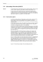
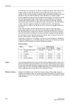
The overexcitation feature serves to measure the voltage/frequency quotient
proportional to the B induction. The overexcitation protection must pick up when the
induction admissible for the protected object (e.g. power station unit transformer) is
exceeded. The transformer is endangered, if, for example, the power station block is
switched off at full-load operation and the voltage regulator does not respond at all or
does not respond fast enough to avoid the related voltage increase.
Similarly, a decrease in frequency (speed), e.g. in island systems, can endanger the
transformer because of increased induction.
In this way, the U/f protection monitors the correct function both of the voltage
regulators and of the speed regulation in all operating states.
Independent
Stages
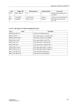
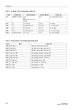
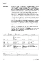
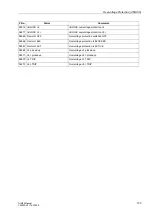
The limit-value setting at address
is based on the induction limit value
relation to the nominal induction (B/B
N
) specified by the manufacturer of the object to
be protected.
A pickup message is transmitted as soon as the induction limit value U/f set at address
is exceeded. A warning message is transmitted subsequent to the
corresponding
time delay.
FNo. 05357
OR
&
Tripping
matrix
U/f
FNo. 05353
&
2
1
t(U/f)
Reset
counter=0
&
FNo. 05370
FNo. 05367
FNo. 05372
FNo. 05371
U
f
U/f heating
U/f cool down
FNo. 05362
TMin
TRIP CMD
FNo. 05373
FNo. 05369

