4 Technical Data
450
7UM62 Manual
C53000-G1176-C149-3
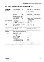
Charge at Polarity Reversal
Q
C
in mAs
- Range
0.00 mAs to 1.00 mAs
- Tolerance
0.01 mAs
Rotor Earth Resistance
R
earth
in k
Ω
- Range
0.0 k
Ω
to 9999.9 k
Ω
- Tolerance
< 5 % or 0.5 k
Ω
R
earth
< 100 k
Ω
for C
e
< 1µF
< 10 % or 0.5 k
Ω
R
earth
< 100 k
Ω
for C
e
< 4µF
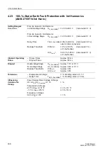
Operational Measured Values for
100-%-Stator Earth Fault Protection (20 Hz)
Stator Circuit Voltage Injection
U
SEF
in V
- Range
0.0 V to 200.0 V
- Tolerance
0.2 % of measured value,
or
±
0.2 V
±
1 Digit
Earth Current of Stator Circuit
I
SEF
in A
- Range
0.0 mA to 1600.0 mA
- Tolerance
0.2 % of measured value,
or
±
10 mA
±
1 Digit
20 Hz Phase Angle
ϕ
SEF
in °
- Range
– 180.0° to + 180.0°
- Tolerance
1.0 %
Stator Earth Resistance (sec.)
R
SEF
in
Ω
- Range
0
Ω
to 9999
Ω
- Tolerance
5 % or 2
Ω
Stator Earth Resistance (prim.)
R
SEFP
in
Ω
- Range
0.00 to 9999.99
Ω
- Tolerance
5 % or (5
Ω ⋅
conversion factor)
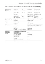
Min/Max Report
Report of Measured Values
With date and time
Reset
– Automatic
Time of day adjustable (in minutes).
Time frame and starting time
adjustable (in days, 1 to 365 days, and
∞
).
Reset
– Manual
Using binary input
Using keypad
Using communication
Min/Max Values for Current
I
1
(positive sequence)
Min/Max Values for Voltage
U
1
(positive sequence)
Min/Max Values for 3rd Harmonics
U
E3H
in Displacement Voltage
Min/Max Values for Power/ Other
P, Q
Min/Max Values for Frequency
f
Power Meter
Four-Quadrant Meter
W
P+
; W
P–
; W
Q+
; W
Q–
- Tolerance
1 %
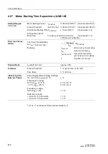
Analog Outputs
(optional)
Number
max. 4 (depending on variant)
Measured Values that Can be Output
I
1
, I
2
, U
1
, |P|, |Q|, |cos
ϕ
|, f;
Θ
S
/
Θ
S TRIP
,
Θ
Rot
/
Θ
Rot TRIP
in %


