


Functions
214
7UM62 Manual
C53000-G1176-C149-3
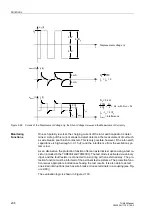
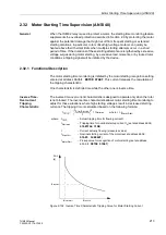
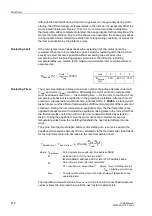
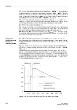
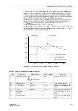
Therefore, if the starting current
I
actually measured is smaller (or larger) than the
nominal starting current
I
A
entered at address
), the actual tripping
time t
trip
is lengthened (or shortened) accordingly (see also Figure 2-102).
Definite-Time
Overcurrent
Tripping
Characteristic
(Locked Rotor
Time)
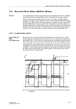
During motor starting, the definite time characteristic is designed to initiate a trip if the
motor starting time exceeds the maximum allowable blocked rotor time t
E
. The device
can detect a locked rotor condition via a binary input (”
>Rotor locked
”) from an
external rpm-counter. If the current in any of the phases exceeds the motor starting
recognition setting entered at address
, and if a locked rotor condition
is detected via a binary input, a motor starting condition is assumed, and time delayed
tripping via the definite time characteristic will be initiated (based on the maximum
allowable locked rotor time). It should be noted that this happens every time the motor
is started and is a normal operating condition that is neither entered in the operational
annunciations buffer, nor output to the control center, nor causes the creation of a fault
record.
The locked rotor delay time (
) is ANDed with the binary
input”>Rotor locked”. If the binary input is still high after the locked rotor time has
elapsed, tripping is performed immediately, regardless of whether the binary input was
activated before or during the delay, or after the delay had elapsed.
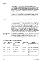
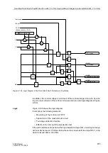
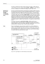
Logic
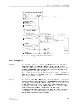
The motor starting time supervision may be switched on or off by parameters. In
addition, motor starting protection may be blocked via a binary input, at which time
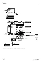
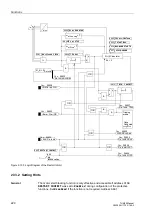
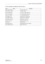
pickup messages and time delays will be reset. Figure 2-103 illustrates the logic for
motor starting protection. A pickup does not create a fault record. Fault recording is
not started until a trip command has been issued.
Figure 2-103 Logic Diagram of the Motor Starting Time Supervision
Fault condition
&
T
0
OR
S Q
R
OR
L1
Rotor locked
Tripping
matrix
I
L1
OR
OR
TMin
TRIP CMD
FNo.
FNo.
FNo.
FNo.
FNo.
FNo.


