


Sensitive Earth Fault Protection (ANSI 51GN, 64R)
185
7UM62 Manual
C53000-G1176-C149-3
2.27
Sensitive Earth Fault Protection (ANSI 51GN, 64R)
2.27.1 Functional Description
General
The highly sensitive earth fault protection has the task to detect earth fault in systems
with isolated or high-impedance earthed star-point. The pick-up criterion is the
magnitude of the (residual) earth current. The magnitude of the residual current allows
earth fault detection, for example, on electrical machines which are directly connected
to the busbar of an isolated power system, when in case of a network earth fault the
machine supplies only a negligible earth fault current across the measurement
location, which must be situated between the machine terminals and the network,
whereas in case of a machine earth fault the higher earth fault current produced by the
total network is available. The measured current may be derived from toroidal CTs or
CTs in Holmgreen connection.
In the 7UM62, the sensitive earth fault detection feature can be allocated to either
input I
EE1
or I
EE2
. This choice is made during configuration (see Section 2.2).
This protection is not suited for detection of high earth currents which may arise in
case of earthed system starpoints (higher than approx. 1 A at the relay terminals for
highly sensitive earth current protection). If this protection feature nevertheless shall
be used as short-circuit to earth protection, an additional, external current transformer
is required as intermediate transformer.
Note: The sensitive earth current protection as well as for the directional or non–
directional stator earth fault protection of busbar-connected machines may use the
same current measuring input (I
EE2
). That means that both protection functions use
identical input currents if address
is set to
directional
or
non-dir. U0&I0
.
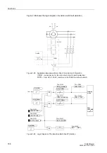
Application as
Rotor Earth Fault
Protection
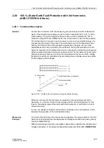
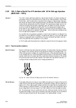
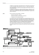
Alternatively, this protection can be used as rotor earth fault protection when a system
frequency bias voltage is applied to the rotor circuit (refer to Figure 2-88). In this case,
the measured current is determined by the magnitude of the bias voltage U
V
and the
capacitance of the coupling capacitors of the rotor circuit.
A measured value supervision is provided for the application as rotor earth fault
protection: The measurement circuit is assumed to be closed as long as a small earth
current
is flowing which is determined by the rotor-earth capacitance. If not, an
alarm is issued after a short delay time of 2 s.
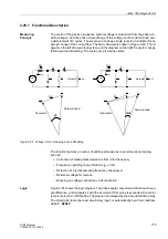
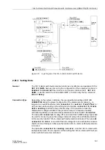
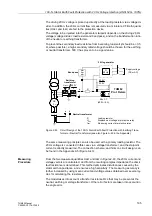
Measuring
Procedure
Initially, the residual current is numerically filtered so that only the fundamental wave
of the current is used for the measurement. This makes the measurement insensitive
to transient conditions at the inception of a short-circuit and to harmonics content in
the current.
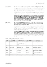
The protection consists of two stages. A pickup is detected as soon as the first
parameterized threshold value
is exceeded. The trip command is transmitted
subsequent to the
delay time. A pickup is detected as soon as the second
parameterized threshold value
is exceeded. The trip command is transmitted
subsequent to the
delay time.
Both stages can be blocked via a binary input.


