Auxiliary Functions
295
7UM62 Manual
C53000-G1176-C149-3
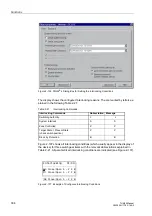
A dialog box displays the texts of all annunciations that have been masked to the
system interface in the matrix. In another column of the dialog box you can specify a
value for the annunciations that you want to test (e.g.
coming
/
going
) to generate an
annunciation as soon as you have entered password no. 6 (for hardware test menus).
The annunciation is output and can now be read both in the operational annunciations
of the SIPROTEC
®
device and in the station control center.
This test can be performed in annunciation direction as well as in command direction.
The procedure is described in detail in Section 3.3.2.
2.45.5.3 Testing the States of the Binary Inputs/Outputs
With DIGSI
®
4 you can test selectively individual binary inputs, output relays and
LEDs of the SIPROTEC
®
4 device. This allows you, for instance, to check during
commissioning whether your station connections are correct.
A dialog box displays all binary inputs and outputs existing in the device, and the LEDs
with their current state. It also shows which commands or annunciations are masked
to which hardware component. In anther column of the dialog box you can switch each
item to the opposite state after entering password no. 6 (for hardware test menus). In
this way you can, for instance, cause each output relay to pick up, and thus test the
wiring between the 7UM62 and the station, without having to create the indications
masked to it.
This procedure is described in detail in Section 3.3.3.
2.45.5.4 Creating a Test Oscillographic Recording
At the end of commissioning, an investigation of the stability of the protection during
closing operations. For this, closing test should be carried out. Oscillographic event
recordings obtain the maximum information about the behaviour of the protection.
The 7UM62 also has the capability of capturing waveforms when commands are given
to the device via the service program DIGSI
®
4, the serial interface, or a binary input.
For the latter, the binary input must be masked with event 4 ”
The oscillographic recording is then triggered when the input is energized. An auxiliary
contact of the circuit breaker or primary switch may be used to control the binary input
for triggering.
An oscillographic recording that is externally triggered (that is, without a protective
element pickup or device trip) is processed by the device as a normal oscillographic
recording, and has a number for establishing a sequence. However, these recordings
are not displayed in the Trip Log as they are not a fault event.
The procedure for this is described in detail in Section 3.4.11.
2.45.6 Setting Hints
Thresholds
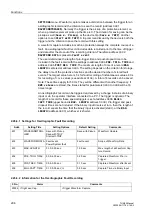
The settings are entered under
MEASUREMENT
in the sub-menu
SET POINTS (MV)
by overwriting the existing values.
Waveform Capture
Waveform capture of faults is executed only when address
has
been set to
Instantaneous values
or
RMS values
. Other settings pertaining to
waveform capture are found under the
OSC.
FAULT REC
.
submenu of the


