90–%–Stator Earth Fault Protection (ANSI 59N, 64G, 67G)
179
7UM62 Manual
C53000-G1176-C149-3
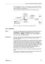
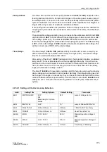
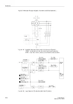
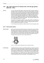
Figure 2-84
Earth Fault Direction Detection with Busbar Connection
Consequently, the loading resistor must be situated on the other side of the
measurement location (current transformer, toroidal current transformer) when viewed
from the machine. The earthing transformer is usually connected to the busbar. Apart
from the magnitude of the earth fault current, the direction of this current in relation to
the displacement voltage can be used for the safe recognition of a machine earth fault
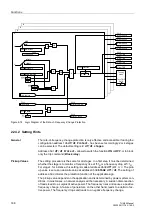
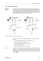
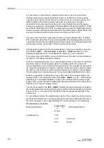
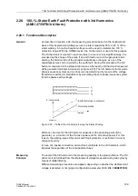
in the case of bus-bar connection. The directional border between “machine direction”
and “network direction” can be altered in the 7UM62 (refer to Figure 2-85). The
protection feature detects a machine earth fault if all three of the following two criteria
met:
−
Displacement voltage larger than set value
,
−
Earth fault current across the measurement location larger than set value
,
−
Earth fault current is flowing in the direction of the protected machine.
Figure 2-85
Characteristic of Directional Stator Earth Fault Protection for Busbar Connection
G
7UM62
U
E
I
EE2
R
L
L3 L2 L1
IE ohmsch
Uen
parametrierbare An
sprechschwelle I ERD>
IE kapazitiv
IE induktiv
Richtung
Netz
Richtung
Generator
einstellbarer Richtungswinkel
IE
öE
I
E
ϕ
E
3I0 >
E
(= U0
)
(= 3I
0
)
Generator
direction
Settable pickup
threshold 3I0>
Settable directional angle
IE inductive
Network
direction
IE capacitive
IE ohmic

