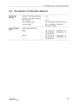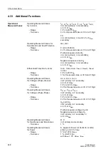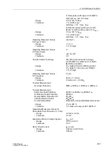
4 Technical Data
440
7UM62 Manual
C53000-G1176-C149-3
4.25
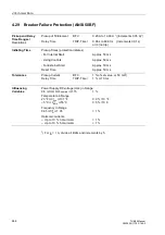
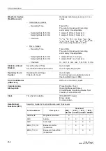
Rotor Earth Fault Protection (R, fn, ANSI 64R)
Setting Ranges/
Resolutions
Alarm Stage
R
E ALARM
3.0 k
Ω
to 30.0 k
Ω
(Increments 0.1 k
Ω
)
Tripping Stage
R
E TRIP
1.0 k
Ω
to 5.0 k
Ω
(Increments 0.1 k
Ω
)
Delay Times
T
RE ALARM
0.00 s to 60.00 s
(Increments 0.01 s)
or
∞
(ineffective)
T
RE TRIP
0.00 s to 60.00 s
(Increments 0.01 s)
or
∞
(ineffective)
Reactance in the
X
COUPLING
–100
Ω
to 800
Ω
(Increments 1
Ω
)
Coupling Circuit (Capacitive)
Resistance in the
R
SERIES
0
Ω
to 999
Ω
(Increments 1
Ω
)
Coupling Circuit
Pickup Value of
I
RE<
1.0 mA to 50.0 mA (Increments 0.1 mA)
Warning Stage
or 0.0 (stage is inactive)
Correction Angle for
W0 I RE
–15.0° to +15.0°
(Increments 0.1°)
Rotor Earth Fault Current
Permissible Rotor
Earth Capacity C
E
For the tolerances stated, and for detecting an interruption of the measuring circuit
0.15 µF
≤
C
E
≤
3.0 µF
Permissible Operating Range of the
20 V
∼
to 100 V~
Injected Voltage
(Warning U
RE<
at U
≤
20 V
∼
)
Times
Pickup Times
– Warning Stage, Tripping Stage
≤
80 ms
Dropoff Times
– Warning Stage, Tripping Stage
≤
80 ms
Dropoff/Pickup
Ratios
– R
E WARN
, R
E TRIP
Approx. 1.25
– Alarm
I
RE<
Approx. 1.20 or 0.5 mA dropout difference
– Alarm
U
RE<
Approx. 5 V dropout difference
Tolerances
– Warning Stage, Tripping Stage
5 % for R
E
≤
5 k
Ω
and 0.15
≤
C
E
/µF
≤
3
10 % for R
E
≤
10 k
Ω
and 0.15
≤
C
E
/µF
≤
3
10 % for 10
≤
R
E
/k
Ω ≤
30 and C
E
≤
1 µF
– Delay Times
T
1 % or 10 ms
Influencing
Variables
for Pickup Values
Power Supply Direct Voltage in Range
0.8
≤
V
PS
/ V
PS nominal
≤
1.15
1 %
Temperature in Range
23 °F
≤ ϑ
amb
≤
131 °F
0.3 % / 10 °F
–5 °C
≤ ϑ
amb
≤
55 °C
0.5 % / 10 K
Frequency in Range
0.95
≤
f/f
N
≤
1.05
3 % for C
E
≤
0,15 µF
10 % for 0,15
≤
C
E
/µF
≤
1

